


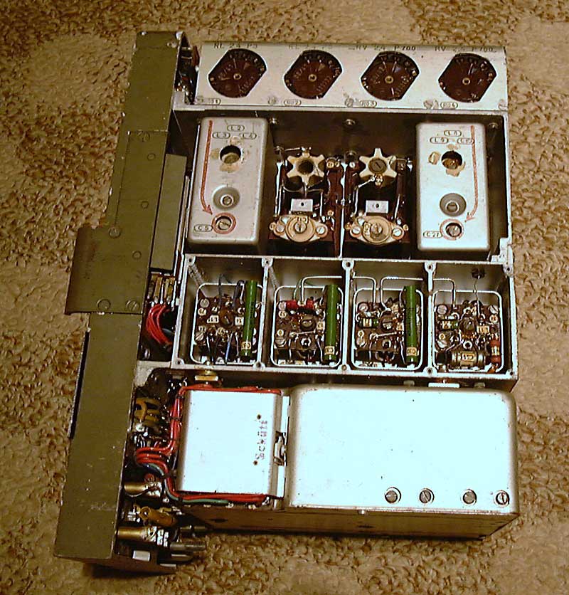
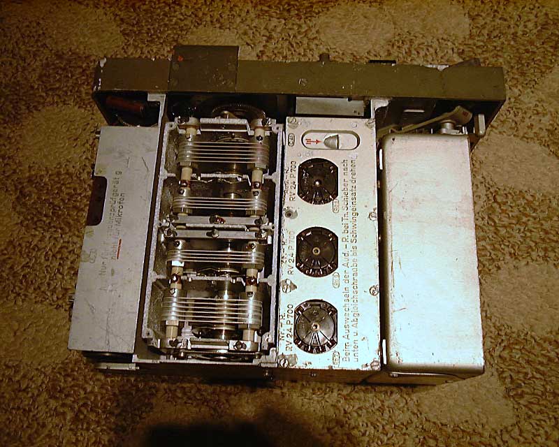
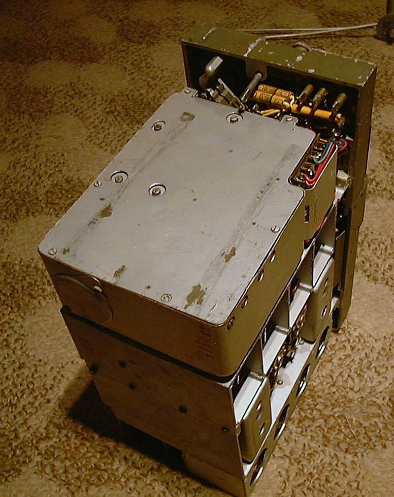
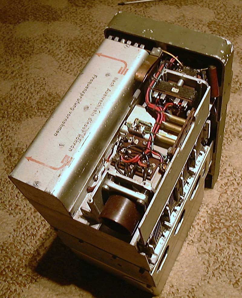
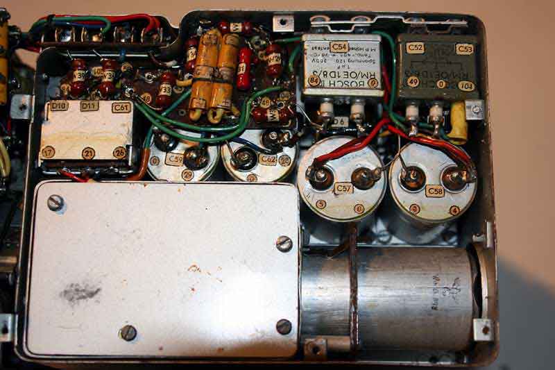
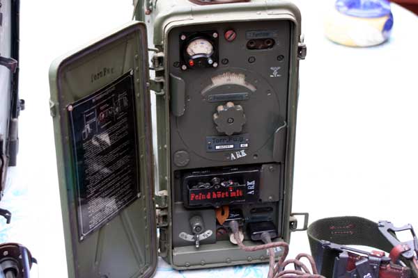
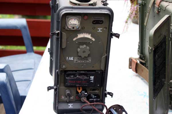
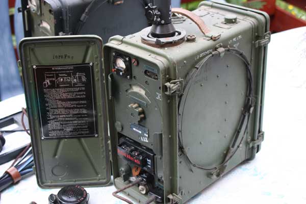
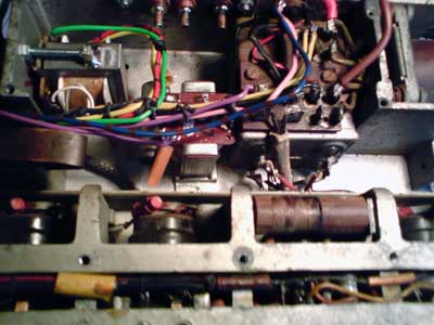
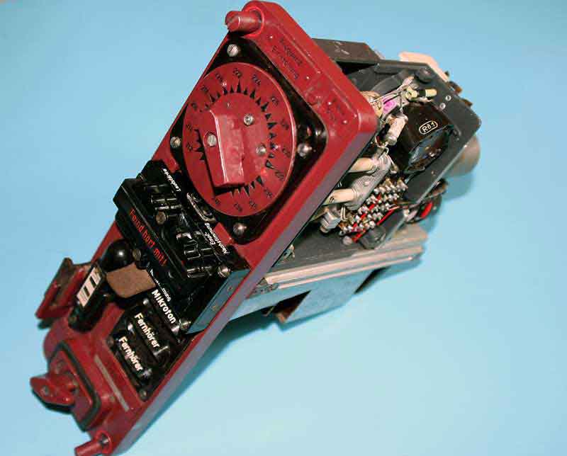
Front Top:Osc R/T IF ampl Freq condensator Bottom vibrator RF and batt con Osc


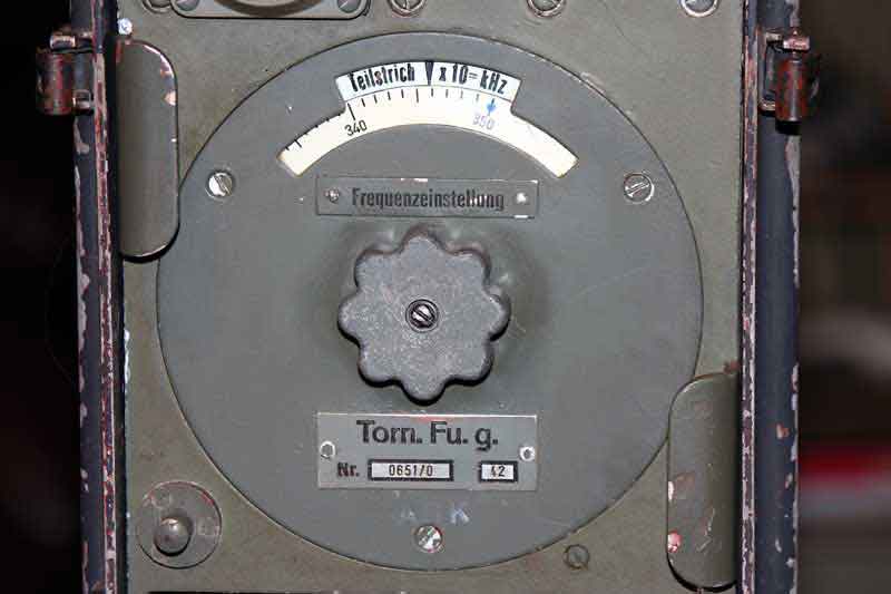
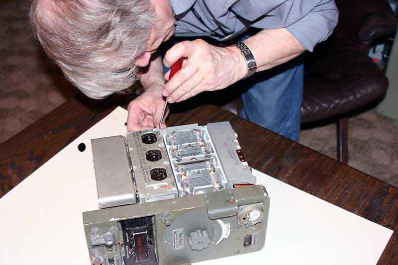
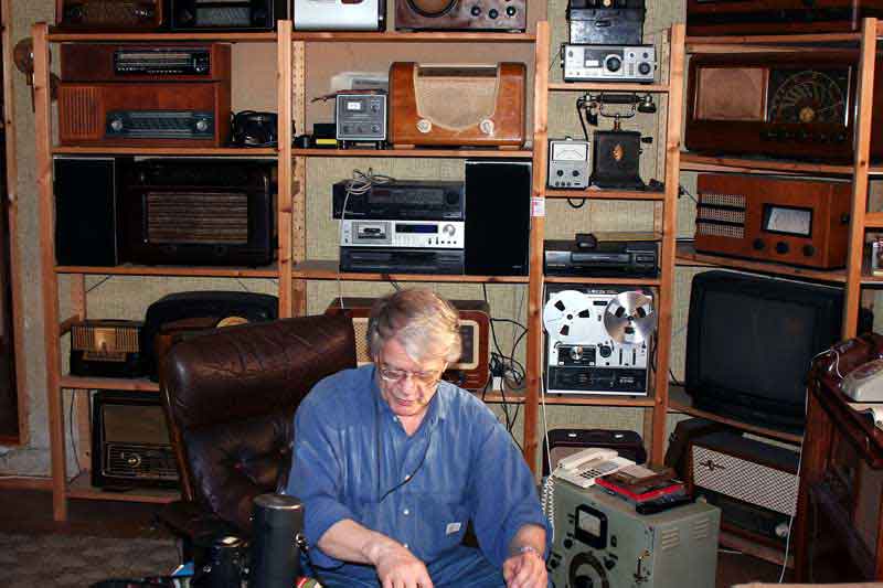
Osc and IF coils Multimeter and Freq adj Working on the unit Vibrator unit
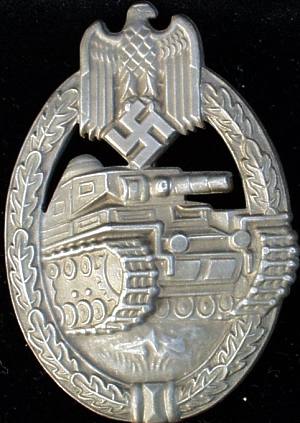

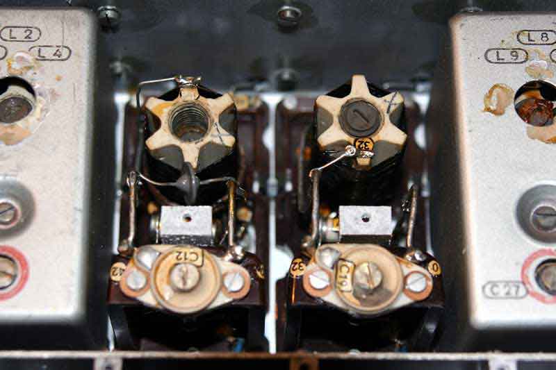
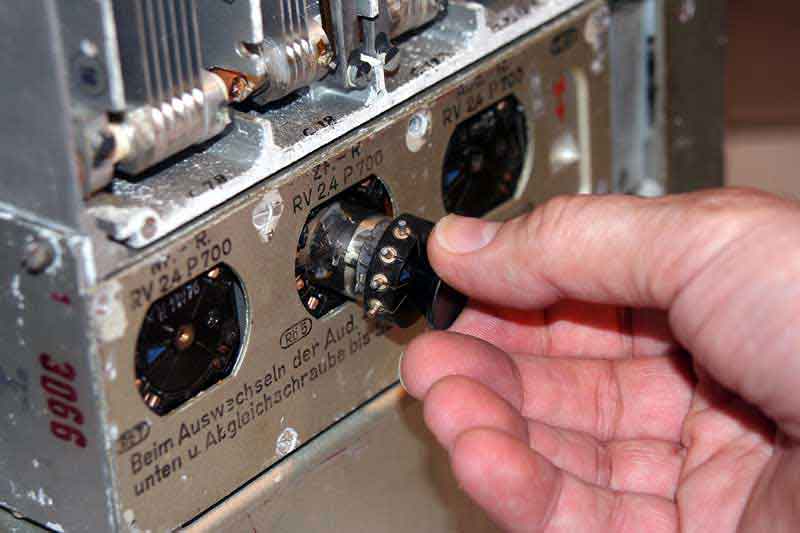
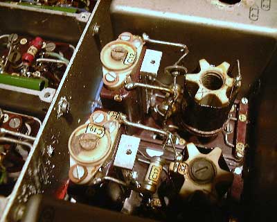
Panzer symbol IF-coils Oscillator Coils TX/RF tubes Tubes Tube changes
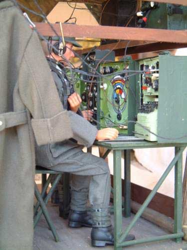

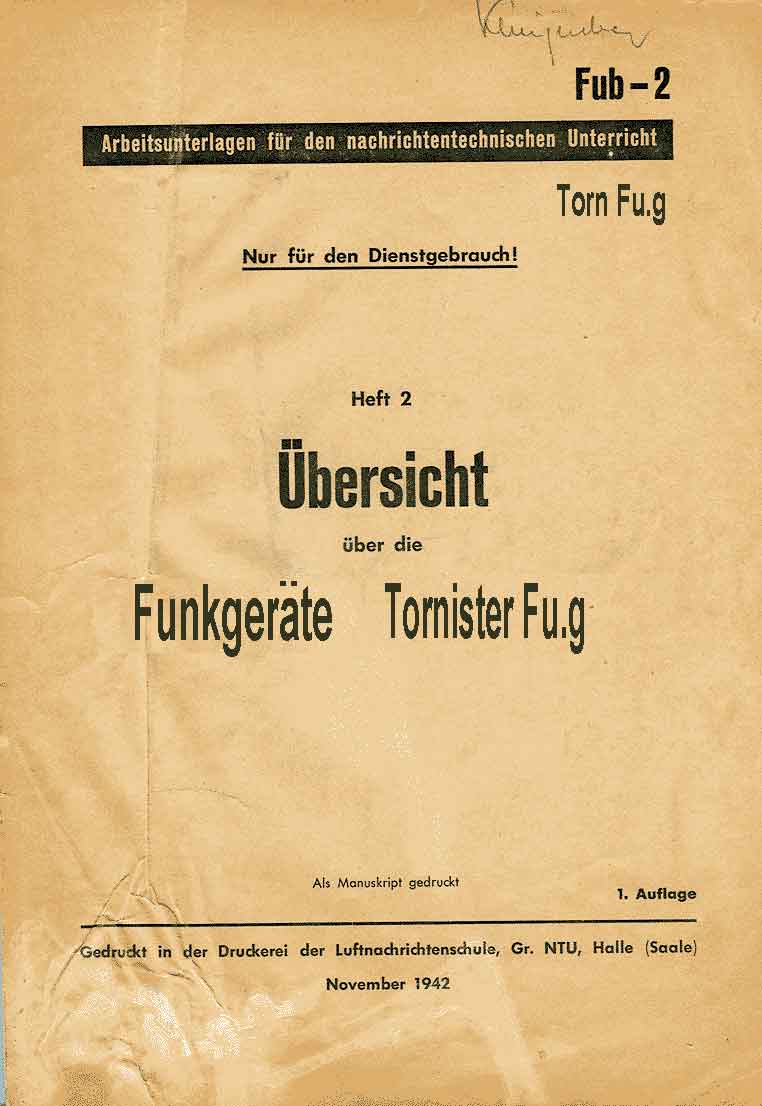
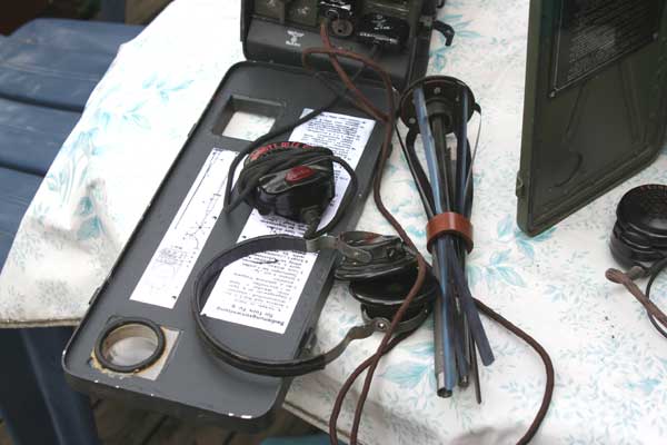
Part of RF Detail of adj-cond Detail of vibrator "Funker" Operation book
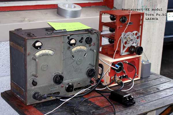
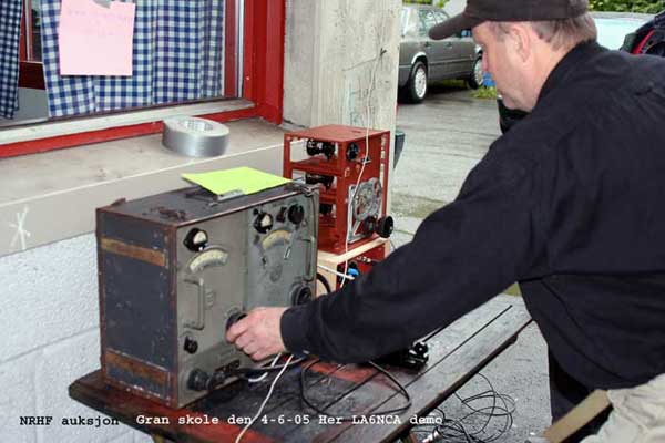
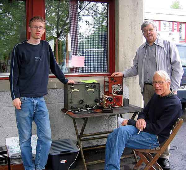
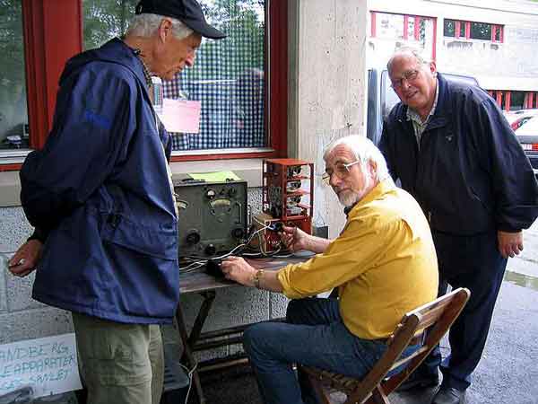
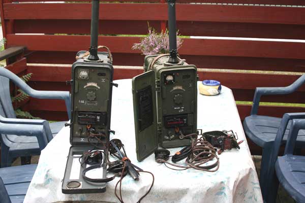
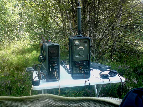
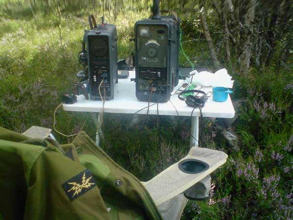
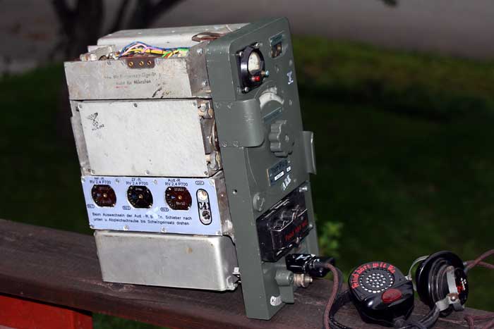
LA6NCA "ON AIR" with Torn Fu.b1 on NRHF Oslo 4-6-05
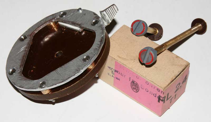
Rohren Torn Fu.g Type Wehrmacht 5 stk RV-2.4-P700 and 2 stk RL-2.4-P3.
Wehrmacht mobile radios
In the mid-1930's the German military standardized the production and use of radio equipment. In order to fight a mobile war, units in the field needed to get orders as fast as possible. On the tactical level, units that could communicate back and forth instantly had a great advantage over those who could not. When Germany invaded France in May 1940, all German tanks were equipped with Tornister E.b radio receivers, and many had transmitters as well. The French and British on the other hand, had only begin to equip their tanks with radios, and only a handful were installed before the battle. Despite the fact that German armored forces were outnumbered two-to-one, and that French tanks were often superior in quality, the panzers were able to sweep aside much opposition due to their ability to coordinate via radio.
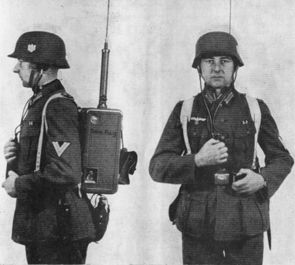
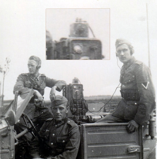
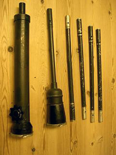
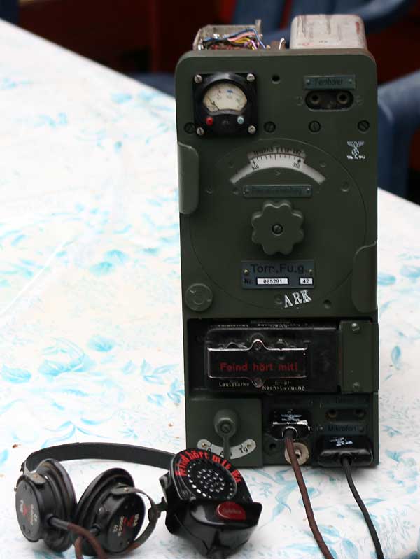
The radio network also allowed artillery and air support to be called down on stubborn enemy positions right away. Embedded within the army were ground controllers familiar with aircraft capabilities and who could coordinate pinpoint strikes when ground commanders needed them. All of this combined to make the German war machine a very efficient, contributing heavily to the defeat of one of the most powerful nations in only seven weeks. The Torn Fu g was a medium wave set of a bit more power and a real super-heterodyne receiver. These sets were sometimes also used in tanks (Panther an Tiger) to communicate with the "Panzergrenadiere". The latter used the set then as a backpack.The antenna like a whip, ca 1.5 meter long, and a coil, adjustable,in the base of it, was like a screw with freq marks.

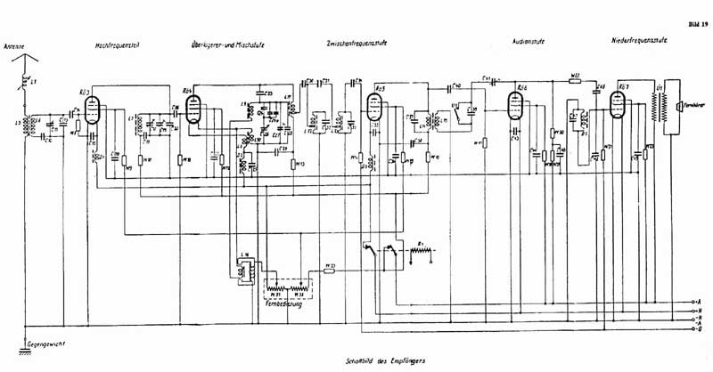


Battery is 2.4vdc NC-28, and high power produced from a syncron-vibrator.The power deliver negativ and positiv voltage to the unit.Highpower ca 127-130 volt dc.The receiver is a straight simpel-superheterodyne,and transmitter an adjustable oscillator followed by AM modulated PA. With the 1,5m whip you may reach a distance about 9-25km between to units.
Torn Fu.k 1942 S:4.5-6.7 E:3.0-6.7 3x RL2.4P3 6x RV2.4P700
Torn Fu.g 1942 1.5W input S:2.5-3.5MHz 2x RL2.4P3 5x RV2.4P700
Torn Fu.h 23-25MHz
Torn Fu.t 2.5-3.0MHz
Torn Fu.i 1943 RL2.4P3 RL4.2P6 9x RV2.4P700
Torn Fu.h 1941 23.1-25MHz 10x RV2.4P700
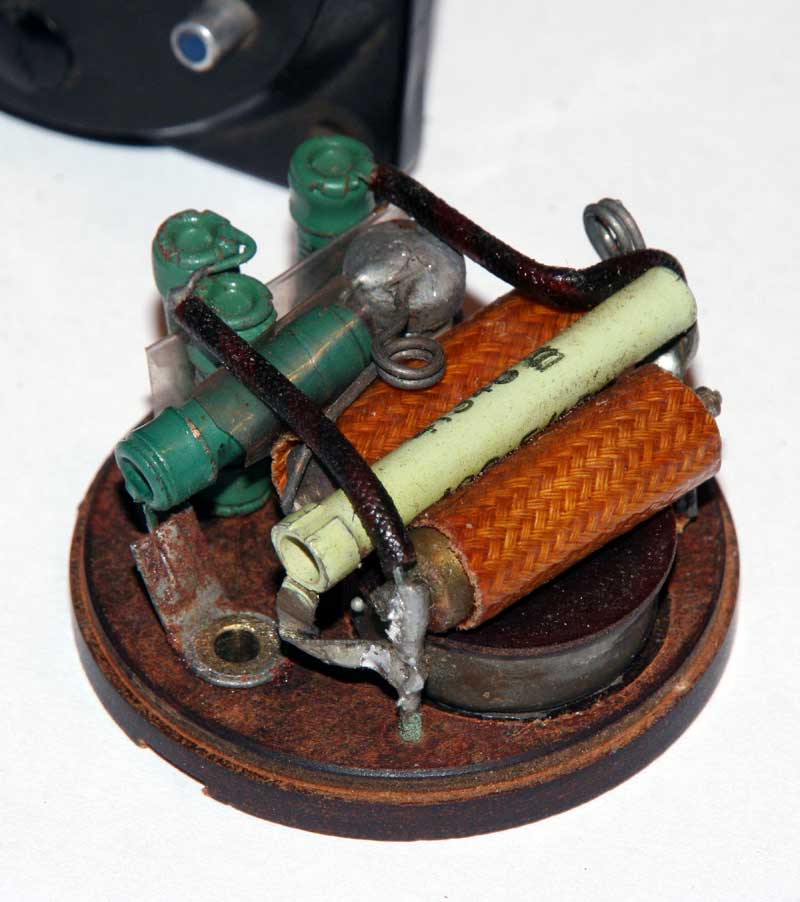
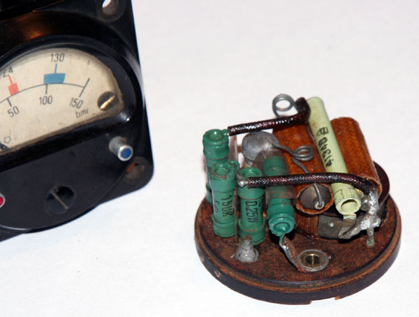
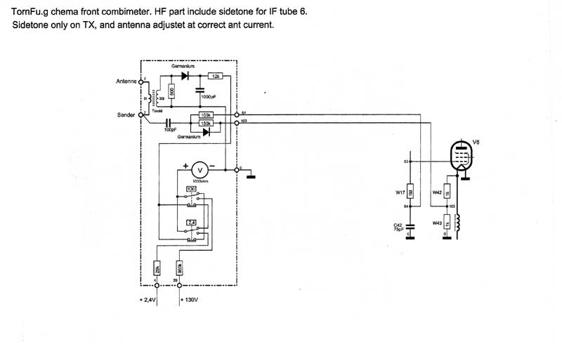
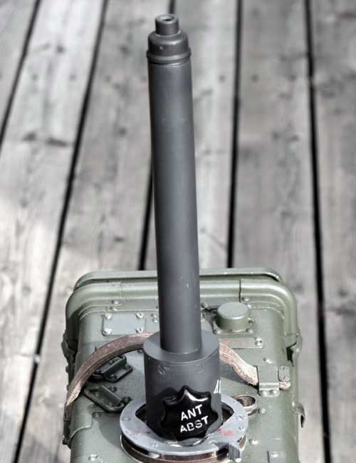
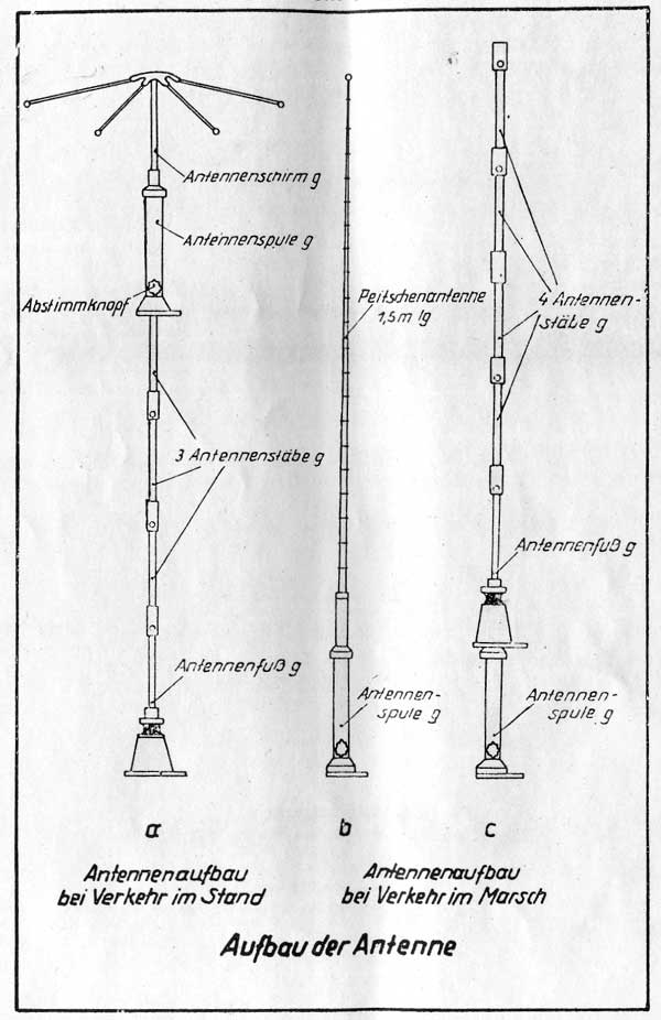
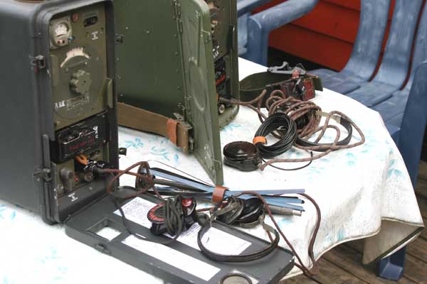
Antennas. ( HF details in frontmeter and TX sidetone when antenna is correct tuned )
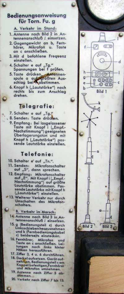
Antennas to the Torn Fu.g (2,5-3.5Mhz) have to alternatives: 1. One 1.5 meter whip with base-coil. 2. 1,2m 4x30cm tubes with a umbrella on the top.This umbrella let the antenne current arise on the antenna for shorter antenna whips.Normal 1.5m antenna lenght.Included into the frontmeter it is a HF unit showing the antenna current when tuning. It is also a HF detector giving the grid change via the AM modulation on TX to IF tube 6. It function let you hear the sidetone (Your own modulation into the earphone ) when the antenna is tuned to max ant current.This way,the operator have control of the tuning when on move.


![]()


![]()
![]()
Radio tubes
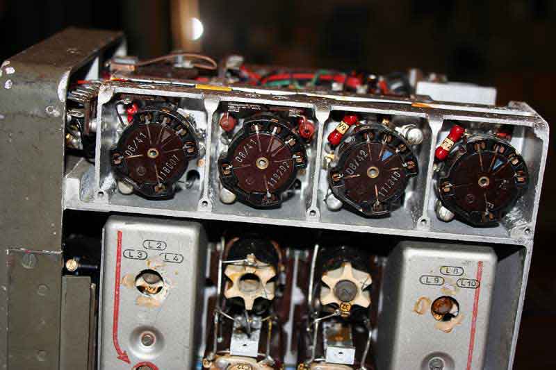
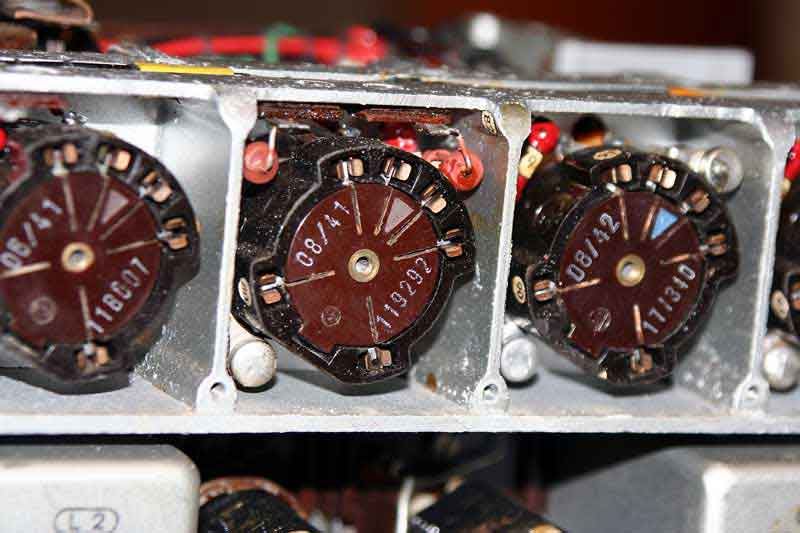
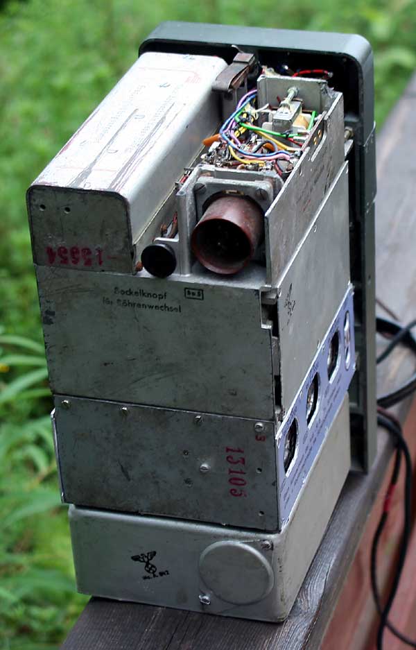
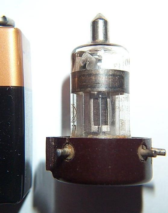
The tubes were especially developed for military equipment. They were miniature types, certainly gauged by the standards of those days, and very robust. The tubes fitted special sockets that completely enveloped them and in which they had to be inserted top first. Nevertheless, the hope that a few types of tubes for all receivers and transmitters would suffice was not fulfilled; by the end of the war some 100 different types could be found on the lists of military tubes. Another feature of German radio receivers and transmitters is that the designers certainly were generous as to the total number of parts used, especially if by doing so potential sources of trouble could be avoided.
Perhaps the most innovative idea the Germans had, was their tube sockets which completely encased the tube, thus making it virtually shock proof. (Physical shock) which contributed to their rugged nature and intended use. Metal tubes which were first introduced in the USA in 1936 and were quickly copied by our Russian allies were not copied by the Germans. Some metal tubes did appear and the R 3 receiver and some of the troop entertainment radios made use of them.
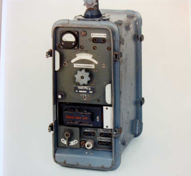
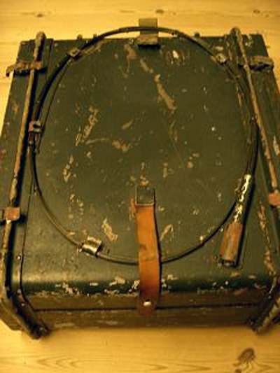
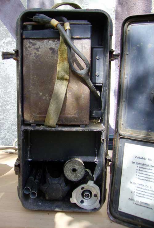
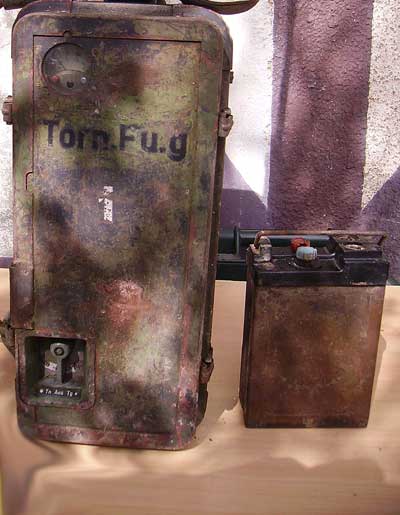
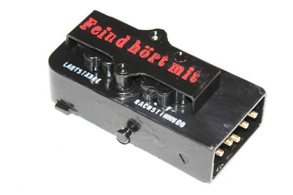
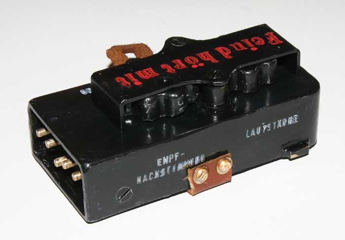
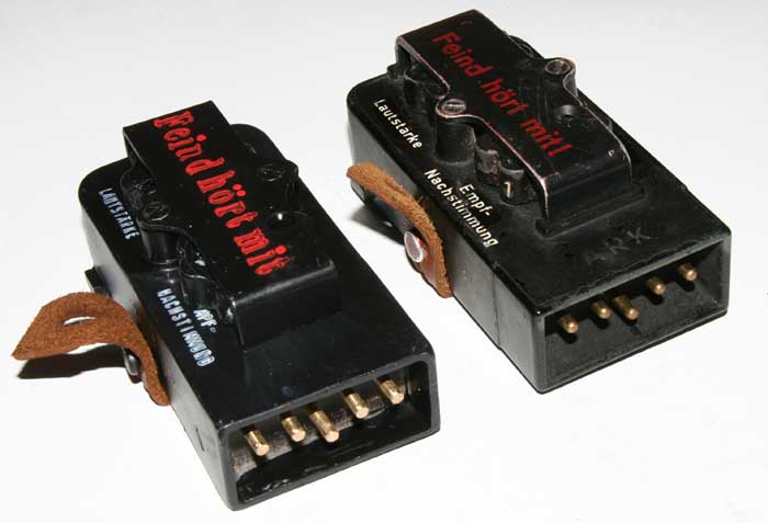
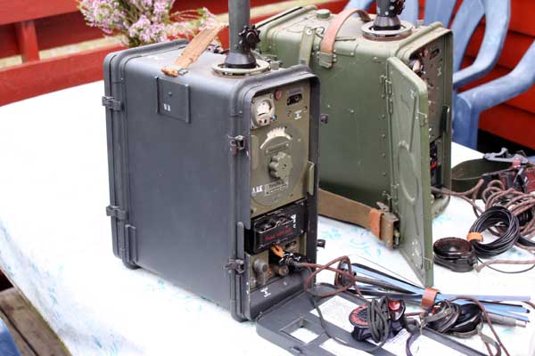
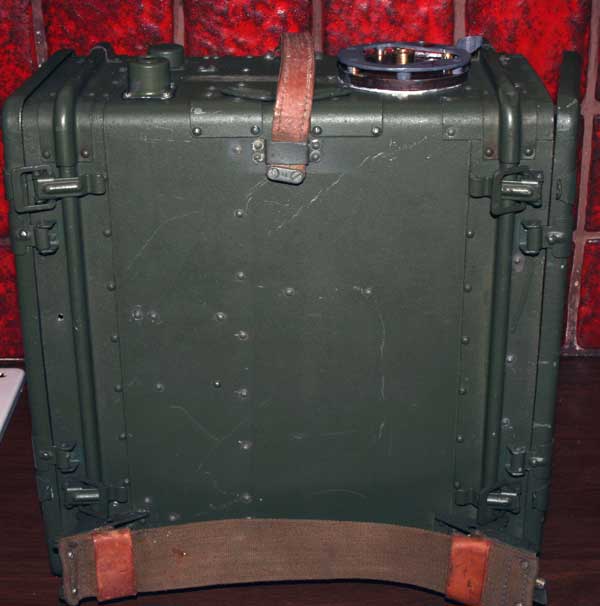
Tornister Fu.g are constructed 1942 and delivered with green military color on front.Later 1944 and out,color on front have a sand-color (light grey).The unit was only operated from the army (Heer) and weight ca 18,3kg all included.High:380x170x320. As earlier, it is produced from many factories,but produced in small quantities.Saba AG produced the first lot of units in 1942.As all manpack radios it is possible to have a 1m controll cable connected.The Control head, control volume and the frequency.
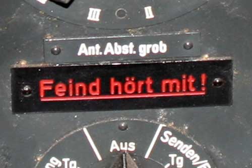
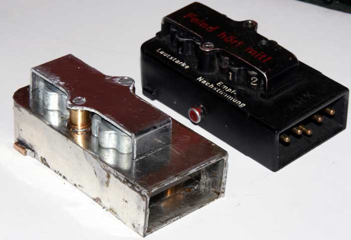
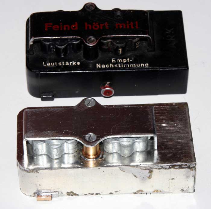
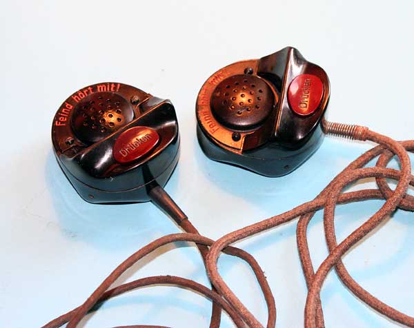
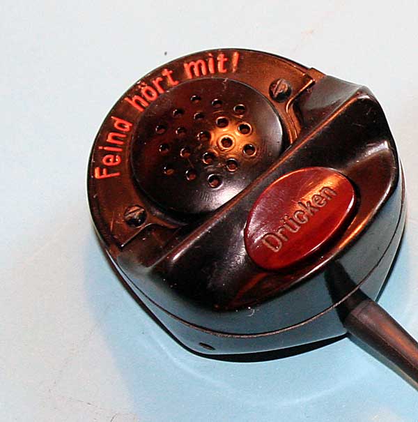
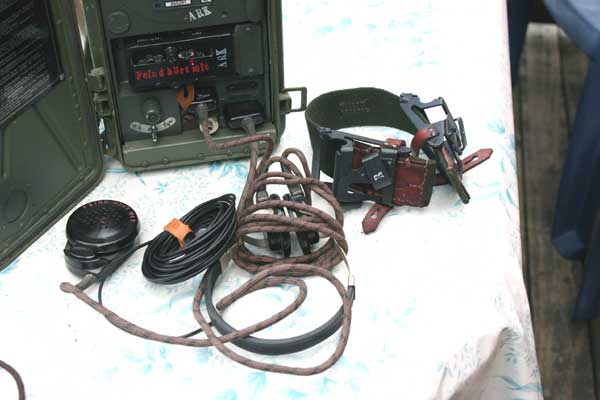
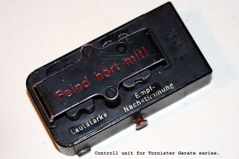
The microphone to Torn Fu.g seems to be a use of a special elements. The normally mic "Feind Hørt Mit" have to high resistance in the carbon element and giving around 40-60% AM modulation. It is ca 300-800ohm resistive. If changed with one 75-200ohm the modulations grade arise to 80-95% AM.I have testet a lot of elements for the best grade of modulations.
| Infantry Radios | |||||||||||||||||||||||||||||||||||||||||||||||||||||||||||||||||||||
|
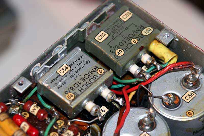
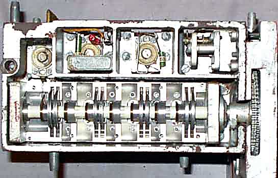
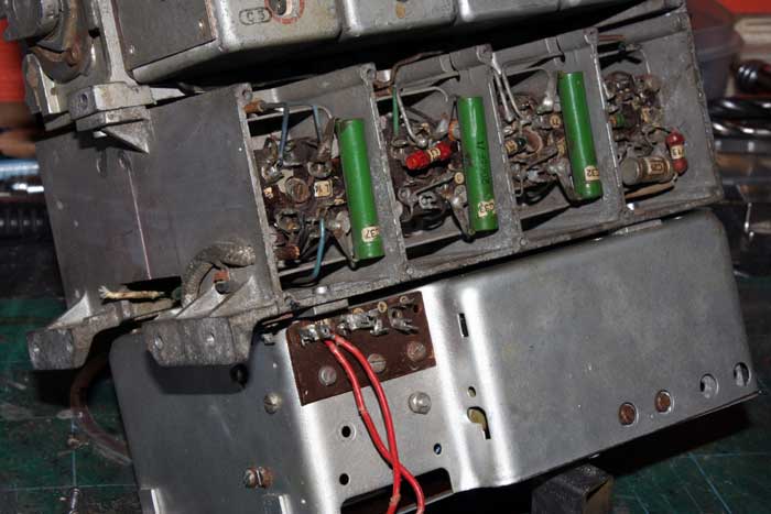
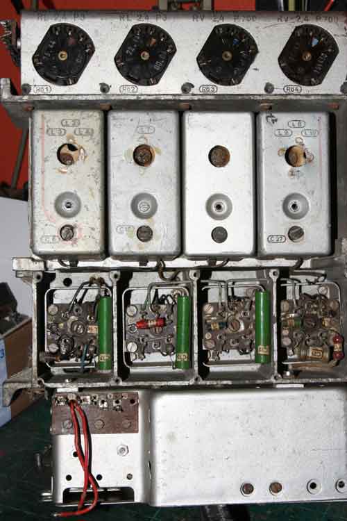
The traditional chassis, so familiar to radio equipment of the past, was never used as such by the Germans. Instead they filled the space in a cabinet in three dimensions. The circuitry of a radio set was divided in a number of units, "modules" we would call them in our day, that could be easily removed and replaced. Usually such a module took the shape of a completely screened box of cast alloy that made it extremely stable, both from a mechanical and an electrical point of view.Inside the box was divided in completely screened compartments that housed the different stages belonging to that unit. The units were combined to a complete set by mounting them into a frame, again made of cast alloy. The electrical connections between the units consisted of multi-pole connectors on the modules, mating with similar devices on the frame. The whole became an extremely strong combination with almost ideal electrical characteristics and easily accessible on all sides for servicing.
Of course, the 1000 year Reich had only a couple years left, so quality of construction could be slighted. The alloy metal has the disturbing tendency to absorb moisture, expand, and then crack or crumble like clay. Corrie Ten Boom, a Dutch woman imprisoned in a concentration camp - aircraft radio factory, recalls in her memoirs sabotaging the radio construction by means of hidden wiring errors. One wonders to what extent German production was set back by the ill will of her army of slaves.
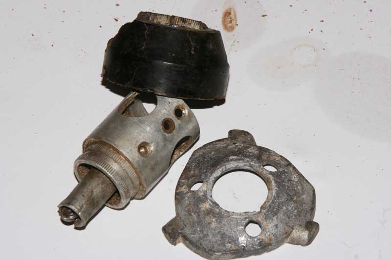
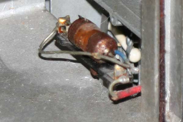
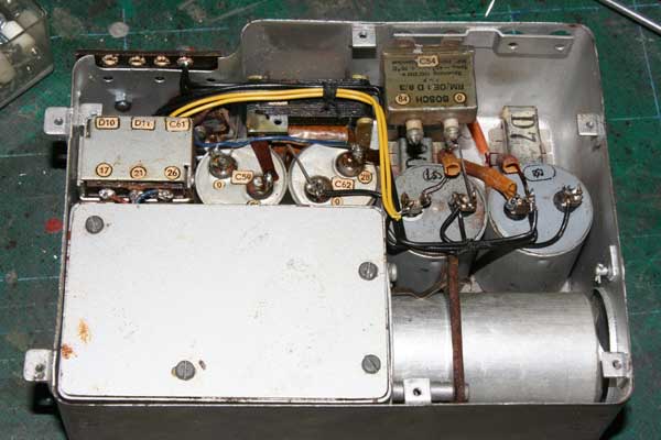
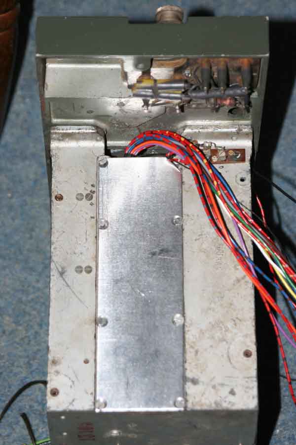
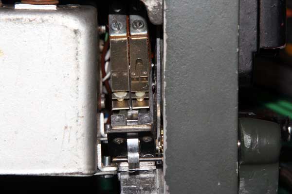
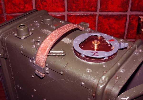
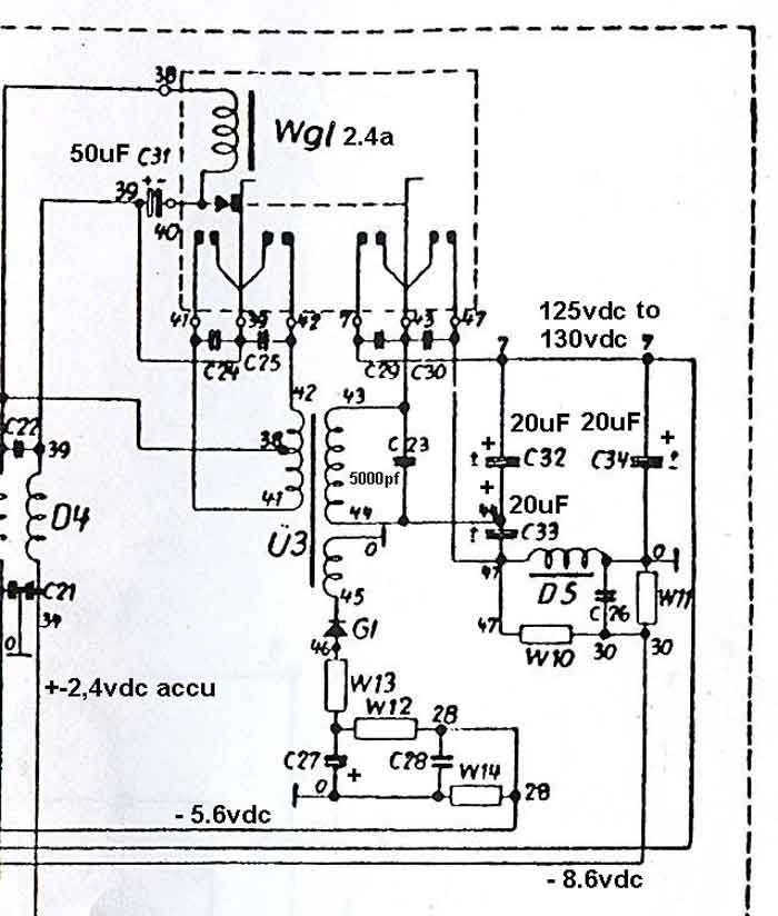
Voltages,from the vibrator depends only how the vibrator works.On the primare side of the trafo,it oscillate around 80Hz,and not critical between 70-90Hz.The secundary side is a voltage doubler.If opening up the vibrator,it is not enough,with adjustment to let it start,but adjustment of the conntacts all around.This is only possible to have done with the TornFu.g opened.connect external battery to it,and turn away the chield-box covering the vibrator unit.Connect a voltage meter to earth and + . When the vibrator can is off,be care when you insert the vibrator socket into the socket.It could be difficult to move out again.Therefore connect a thin wire under the socket to pull it out again.No, do you adjust the vibrator to giving around 128-130vdc in Receive mod.Transmit mode pull down the voltage to ca 110-112vdc.Normally you need to push and pull out the vibrator many times for adjustments. Finished .
The most of the vibrators opened and fixed only to run again,giving ca 112-114vdc in Rx and 87-93v Tx ,this let the radio work very poor.Some other thing to be aware of,is the battery connections inside,from battery cable to the connections box. This points have a lot of corrosions. (New 112-114v and readjustet carefully,128-130v ca 80Hz pendel)
Project: Mechanical Vibrator GWl 2,4a
The mechanical Vibrator type GWl.2,4a ,let us starting a project, as, posebility to change the mechanical type with a electronic one.First making a print board small anough, to fit inside the orginal vibrator can.LA4JH first starting testing a lot of components,but it was a problem with the low voltage, 2,4vdc, to the switching felt-transistors and IC to controll the process.Therefore it was made a power unit giving 5vdc to the operations, included on the printboard.The unit swiching, with ca 80 hz, on primary side of the transformer.
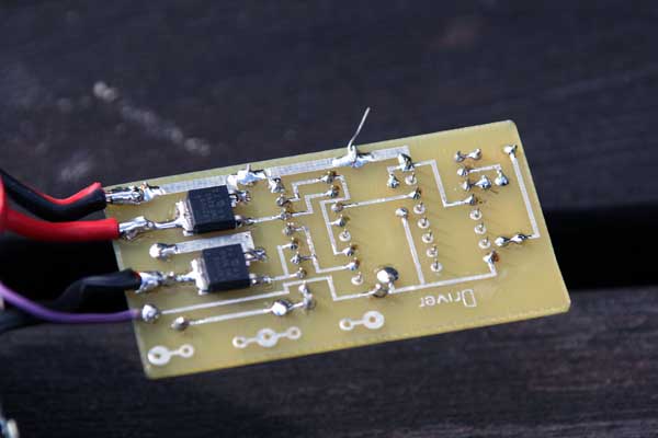


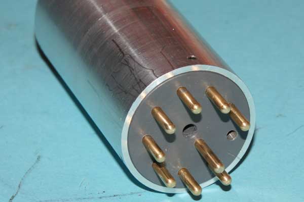

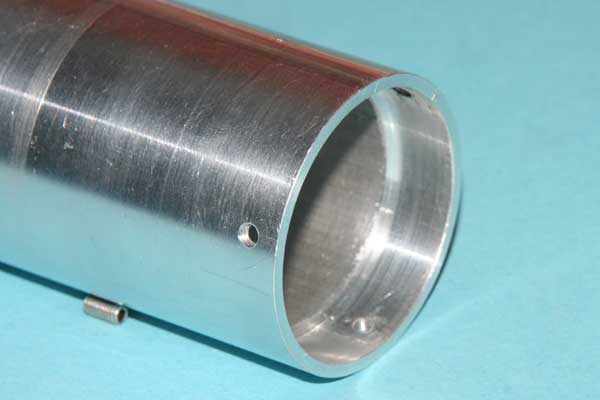
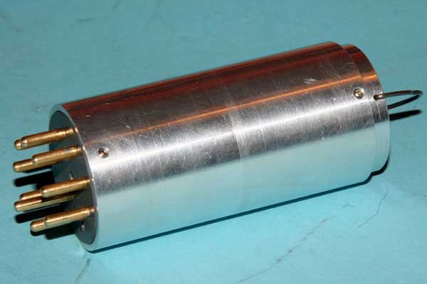
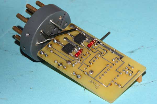
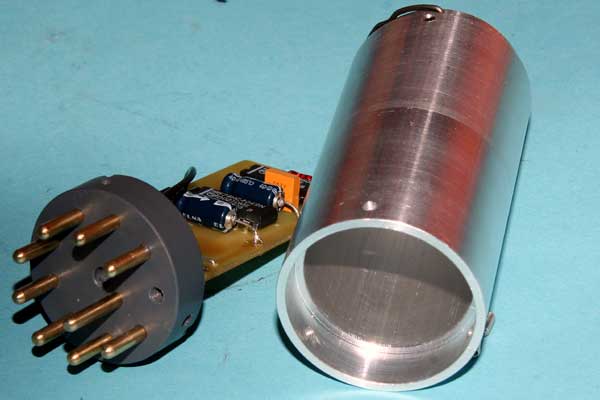
The new vibrator can is made of allu-tube 5mm thick.It is profiled in each end. The socket is made of plastic with 3mm brass connectors.This can is made only for testing the electronics.Normally we use the ordinary vibrator can.This model of electronic vibrators work very well with Tornfu.g and other German equipments,where 2.4vdc + is feed to the center of the primary side of the transformer.Feldfu.b/b1/c/f/h,have 2.4vdc minus, feed to the center of primary side of the transformer. So,here it is necessary to bild a new electronic and card with components.The new "vibrator" giving better HT voltage from orginal. The orginal giving around 140vdc on RX and 128v TX ,if the mechanical vibrator is new.The electronic giving around 145-150vdc, as seems to be more right voltage, and stable transmitt/receive functions. This vibrator is not necessary if the unit only is standing death as collecting unit.LA4JH working on the electronic vibrator for Feldfu series.
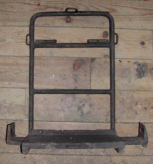
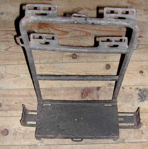
Mounting bracket Torn Fu.g and others,for vehicles. ? (Panzer)
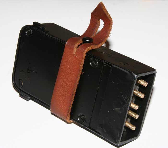
The Torn.fu.g mounting bracket is very selden to see. It is for the most lost in the field military vehicles. It is looking like a "L" made of iron/allu tubes.It is about 300cm wide,380cm deep and the "L" 180cm.On the top it is many leather holes .In the bottom to slides on each side for the connections.(Same as for the rest belt connectors). 1 leather strop,going from right side on top to the lower "L" . The pictures of the bracket are for Torn Fu g and Feldfu b / c and f. It seems to be a general bracket for other types of manpack equipments to.This one was found in a river near Normandie.It is German,but...what?

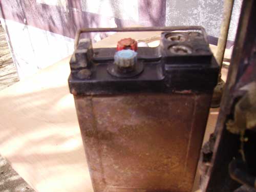
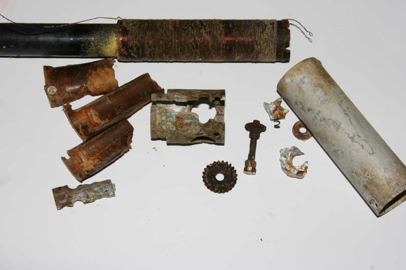
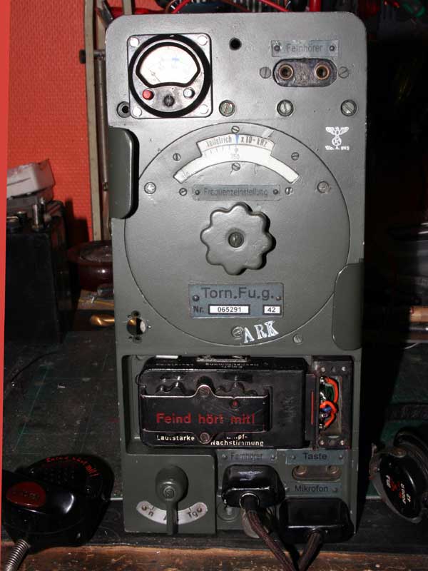
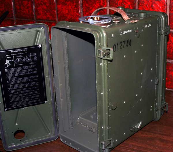
Restaurations Torn.Fu.g (As usual the most radios from the German WWII, must go through a heavy renovations before it works again.Corrosion make them unusable,and the most electrolytic condensers must be changed.The battery NC-28 was made of a iron box,and it was in the most cases rusty,and holes in it.)
I got this summer (April) a Torn.Fu.g in a very bad condition. The unit was stripped for the main wires and the the main relay was not working (2,4v). Some of the IF transformators was broken (650Khz). The main power and Tn/Tg switch was absent. The mod transformer was absent besides the choke D5 in the AF unit. All the tubes where onboard well working. The controlbox was absent like some covers.
![]()
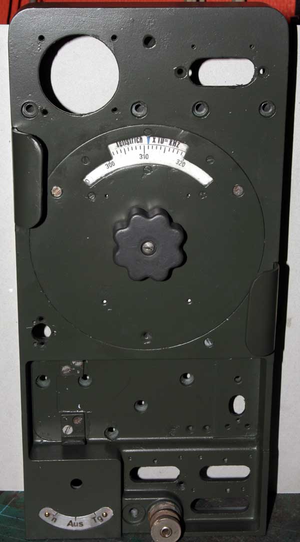
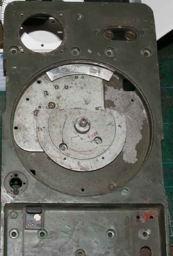


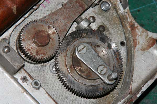
![]() Then,the work begin. First I demounted the front and
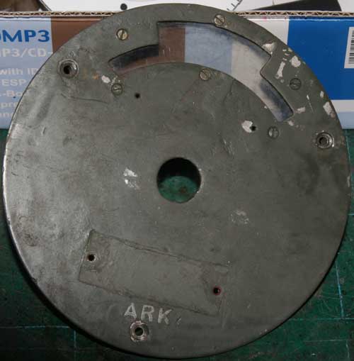
cleaning all parts..Making a new scale,and
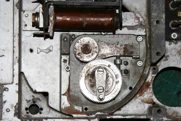
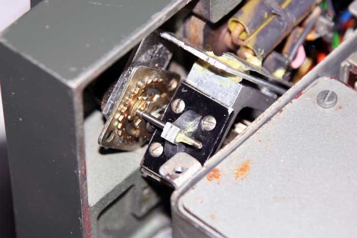
remount the cog wheels. This was not adjustet. Then the On/Off-TN-Tg switch must
be made.It was made of old German telephone
board switch included a 90 degrees 6mm shaft through the hole. Then,the
2,4v relay must be rewinded to work
again on 2,4v. The modualtions transformer 1:10 was specially. This I rewind with
4000 turns / 400 on a new German, empty transformer.The same with the chocke D5.
The instrument was adjustet and a new ferritcore to the antenna current
mesurments was made.Next was making the
antenna foot for the box,and the special screws for fasten the Torn.Fu to
the box.The antenna itself is a "Coilresonator" 325uH.This is adjustet with a variable condenser in series between the PA and output on the bottom of
the coil.The coil is wired on a pertinax tube .This way it is possible to tune the antenna between 2,5 and
3,5Mhz.The condenser tunes to maximum current showing on the front-meter.It is
importent with a ground connections (a Y ca 3m long as backpack,and earth ground
if transmitting as stationary mode).The
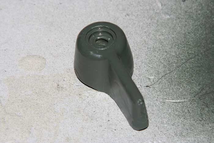
controlbox was another project
including to mould the knops and end connector.It was not possible to get signal
through the MF unit (0,650Mhz).After some time,it was found a broken condenser
200pf. Changed it,and it works.
Then,the work begin. First I demounted the front and
cleaning all parts..Making a new scale,and
remount the cog wheels. This was not adjustet. Then the On/Off-TN-Tg switch must
be made.It was made of old German telephone
board switch included a 90 degrees 6mm shaft through the hole. Then,the
2,4v relay must be rewinded to work
again on 2,4v. The modualtions transformer 1:10 was specially. This I rewind with
4000 turns / 400 on a new German, empty transformer.The same with the chocke D5.
The instrument was adjustet and a new ferritcore to the antenna current
mesurments was made.Next was making the
antenna foot for the box,and the special screws for fasten the Torn.Fu to
the box.The antenna itself is a "Coilresonator" 325uH.This is adjustet with a variable condenser in series between the PA and output on the bottom of
the coil.The coil is wired on a pertinax tube .This way it is possible to tune the antenna between 2,5 and
3,5Mhz.The condenser tunes to maximum current showing on the front-meter.It is
importent with a ground connections (a Y ca 3m long as backpack,and earth ground
if transmitting as stationary mode).The
controlbox was another project
including to mould the knops and end connector.It was not possible to get signal
through the MF unit (0,650Mhz).After some time,it was found a broken condenser
200pf. Changed it,and it works.
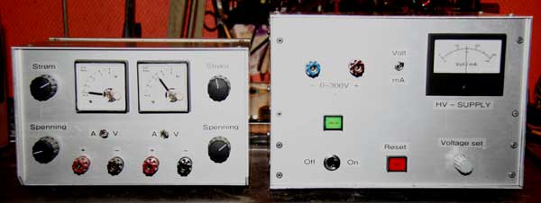
The power supply delivering (battery ca 2.50vdc) high voltage ca 160vdc on receive.The grid negative voltage (-G) to the IF ampl ca -2.8vdc,and to the transmitter PA grid via mod tranformer -36vdc.This grid going to ground in CW mode.Then giving more power output to antenna.The transmitter tube RL2,4P3 seems to be difficult to get.If this tubes is weak or gone,it is possible to have them changed with RL2,4P2.This tube is smaller (shorter) and must have a 12mm long tube split (5mm to 7mm) mounted on the grid top.Then the negative voltage -36v raising to -80v. (change some of the resitors in the power unit).It is done for correct modulation.RV2,4p700 work well as oscillator tube to.The high voltage in transmit going down to ca 120vdc


Controllbox ended.


 Then it came to the end, with the controllbox.Problems with it,
was to get the variable potmeters,500k lin and 50 ohm lin .It seems to no one
produce this old pots models today.
Then it came to the end, with the controllbox.Problems with it,
was to get the variable potmeters,500k lin and 50 ohm lin .It seems to no one
produce this old pots models today.
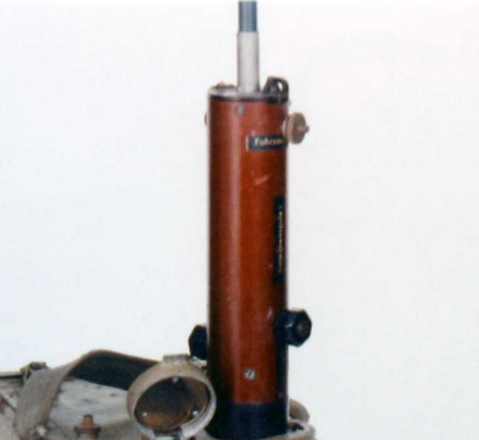
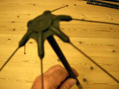
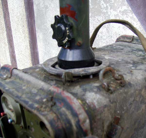
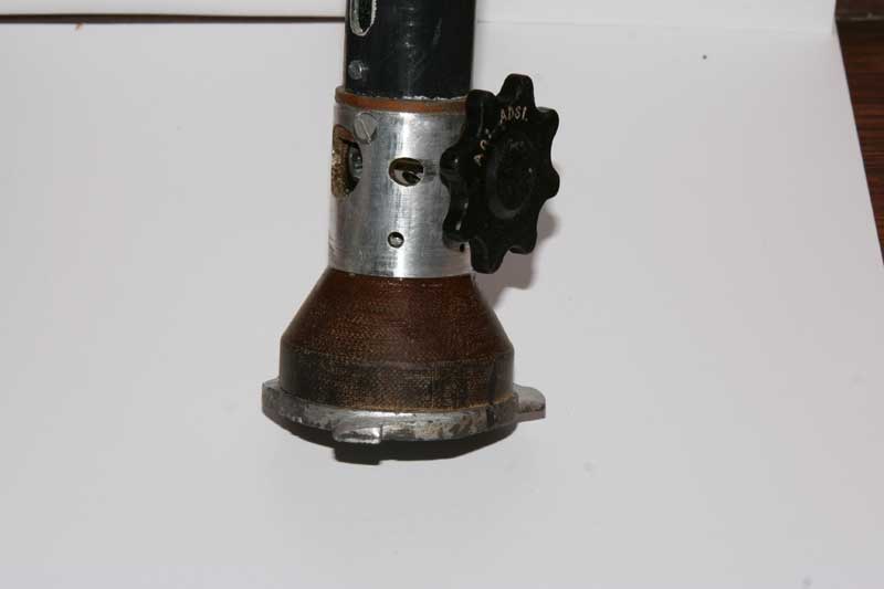
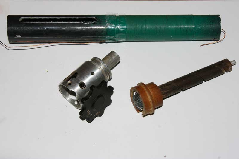
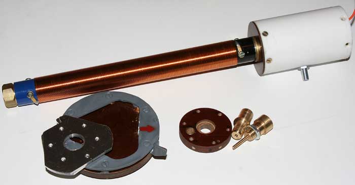
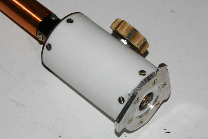
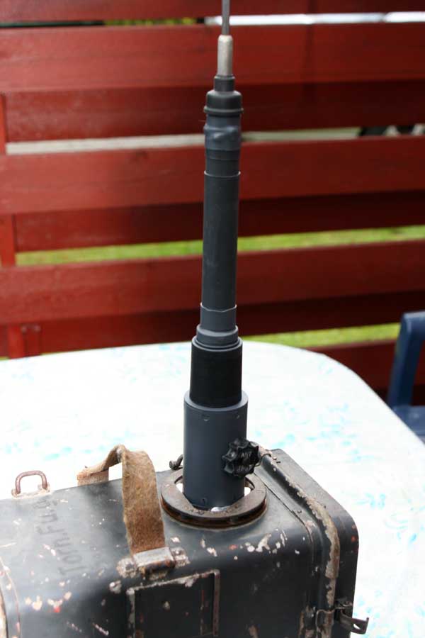
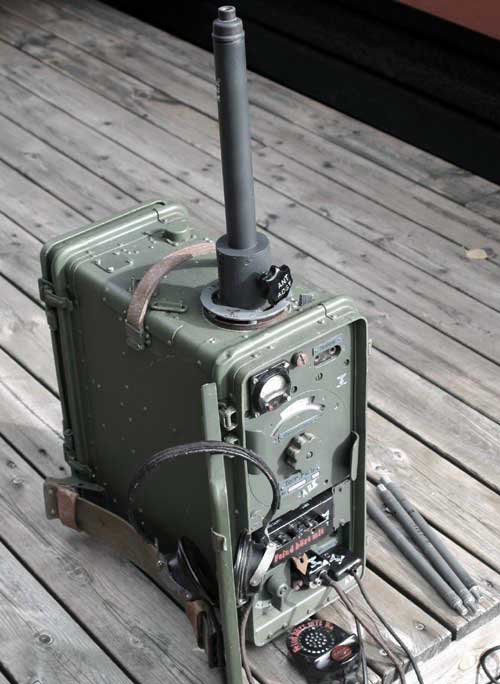
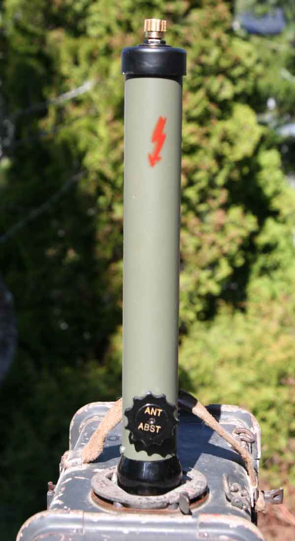
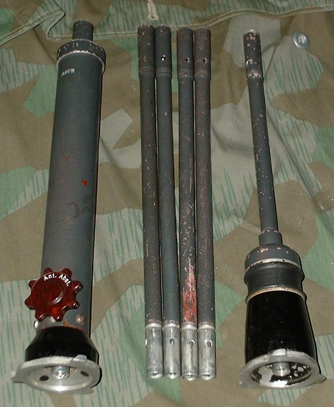
Antenna.
The antenna to Torn Fu.g was a little tricky to make. It was very little about it in instructions books etc from Wehrmacht.Only the tuning instructions.LA4JH was helping me with this antenna part.The box connector was making of me.As seen on the picture,the coil would be covered with a 30mm fiber tube later.The antenna was testet in this mode.On the top of the coil,we mounted a 1.5m whip.The antenna current was on the Torn Fu.g meter going to the middle in phone, and a 1mm from top on Tg (CW).It covered the 2,5 - 3,5Mhz band without no problem.It seems the antenna impedance is very low,about 8-12 ohm in feeding point.. .This antenna was not made for a replica but what could be done, to get a better antenna than the original.Cover the band better and get higher antenna current to the 1.5m,and 2,5 m whip. It was successfully.Later after finishing the Feld Fu.g project.The main problem with this short antenna (1,5m paitchantenna) was the surounding capacity around the lower coil part.The operators steel helmet disturbing this coil if he do not held his head easy.Originally the German make this foot (coil) adjusting a slider up and down the coil.The slider was made of alluminium tube ca 12cm long.On the upper part sorrounding with conntactslides (3 pieces).This shorten the coil with ca 12ohm impedance.The field around the lower part was minimal with this metode.On the other way,a better way was to adjust it with a condencer in bottom of the coil.But the field around the foot arise. If not working as manpack this giving more power to the antenna if stationary.
The test antenna (Only made for testing of the radio-unit)

![]()
![]()
![]()
![]()
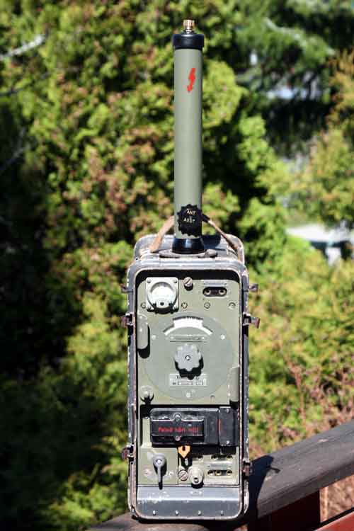
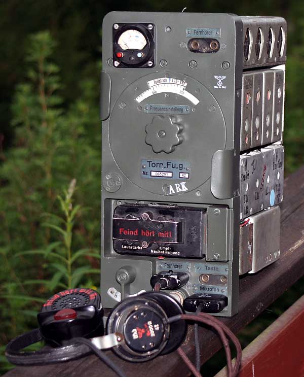
The Torn Fu.g beginn to work again, after 65 years.
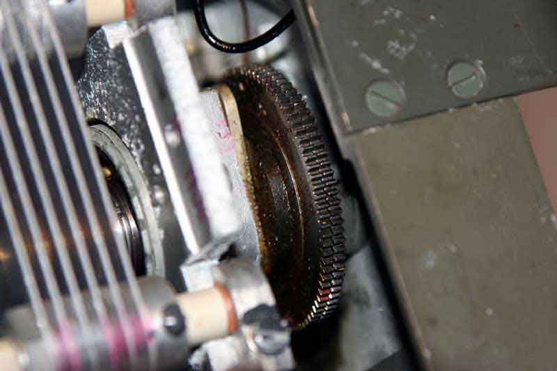
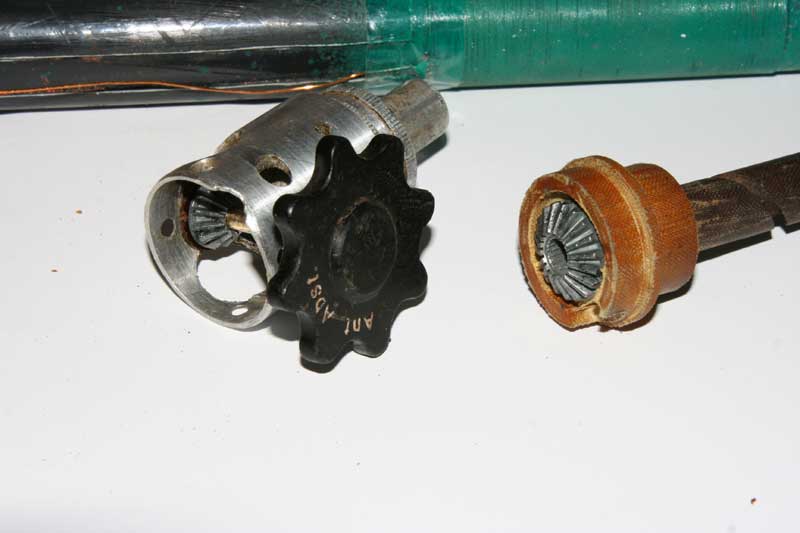
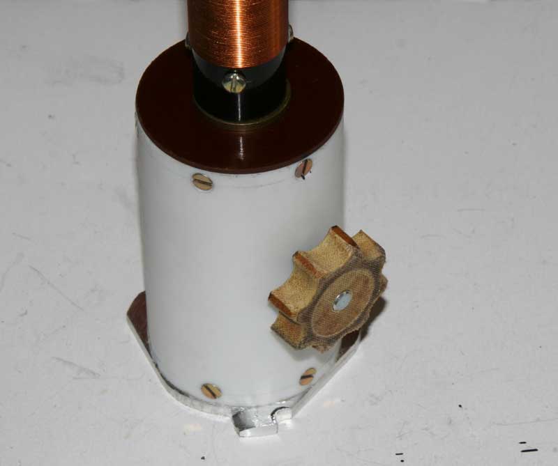
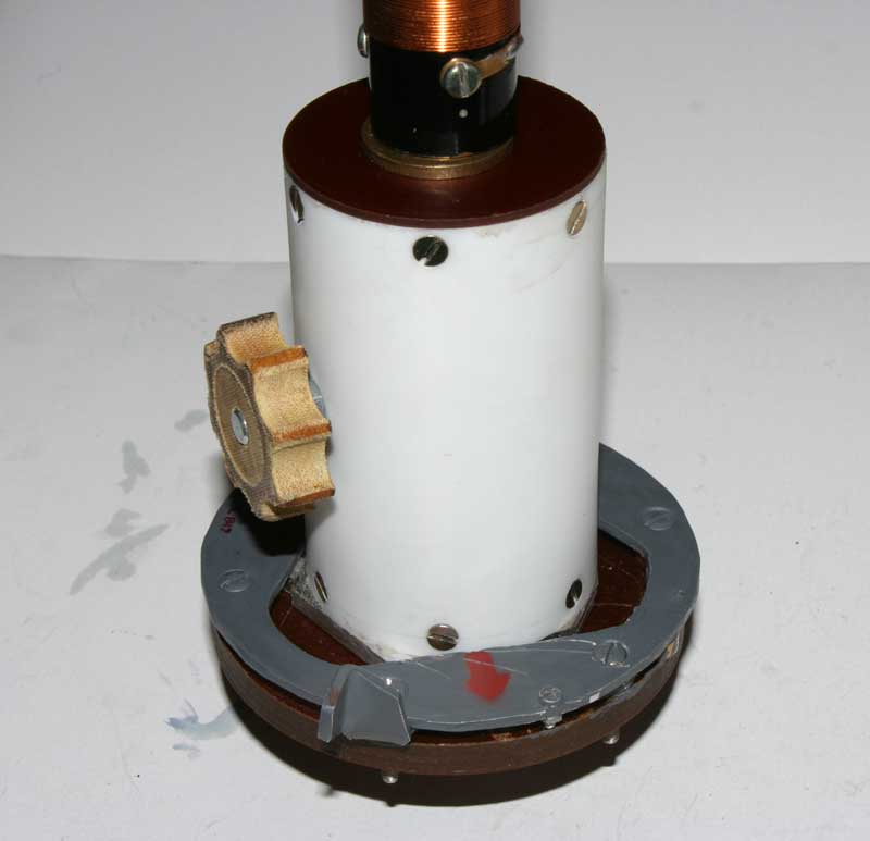
The cog wheels,2 pieces,was adjustet towards the main handle arm from the adjustment condensator on main chassis. This 2 wheels was adjustet a bit besides each other with help of a included steel spring. This is done to remove all the glitch in the tuning wheel. Then,I beginn with all the cable wirings in the radiounit.I working 3 weeks with this wiring.
Now,the radio working as new on transmitter and receiver.Frequencies is adjusting tracking together from 2,5 to 3,5 Mhz.I am starting, working with radio box and the antenna system. The antenna cosist of a bottom coil ( 325uH) with a diameter ca 22mm and 16cm long.In the bottom, a adjusting condenser, making the right antenna impedance.The "Q" on the coil measured ca 290,and was very sharp to tune.
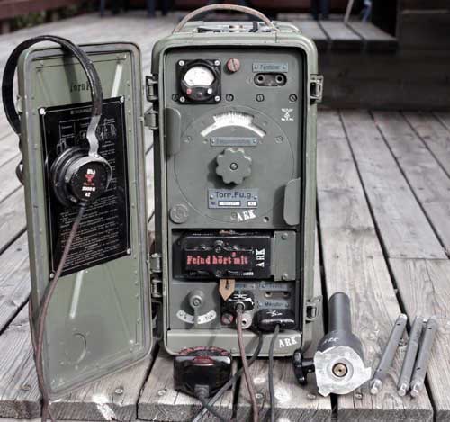
Was is done to the Torn Fu.g?
1. All the wiring are new in the unit. 2. On/off switch is new. 3. All the cogwheels are adjustet. 4. New Frequency dial new. 5. Painting of the front. 6. 2 new screws for the box mounting. 7. New power connector and new main radio box. 8. Antenna foot on the box made new. 9. Antenna made new. 10. Controllbox new. 11. Rewind the mic transformer incl transformer choke 5. 12. 3 new covers for modulator,MF and HF parts in the radio. 13.Disapearing components in the power unit inserted.Filter chokes,component board and filter board. (most org parts inserted). 14. New org vibrator unit. 15. Antenna ferrite-inductor wired and mounted. 16. All new adjusting condensers in RF and TX-PA (4-18pf),and new coil cores.) 17. Changed 1 broken capacitor in MF unit (200pf cermic,green) 18. The MF unit have many broken mecanical parts on the coils bakelite-cans.All where repaired. 19. Adjusting the receiver and transmitter together for "netting" the same frequency.Including PA/RF adjustments for maximum between 2.5 -3.5Mhz.
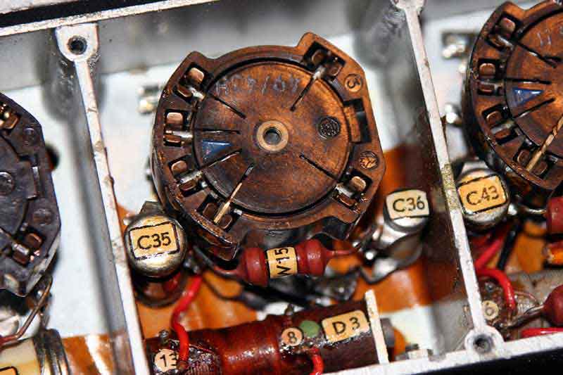
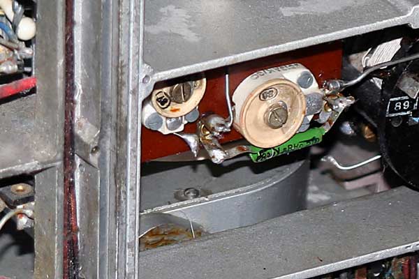
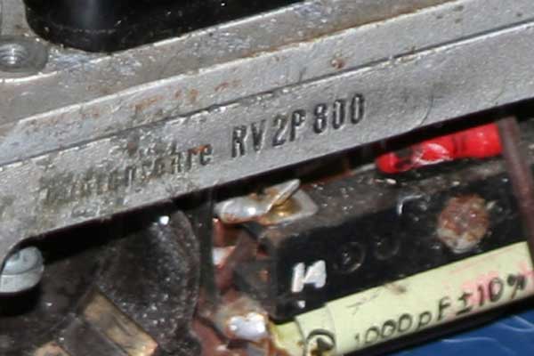
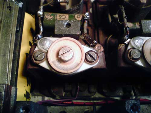
Frequency adjustments Torn Fu.g
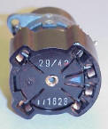
The radio must be readjusted. The variable capacitor (C4) the part, near the front, has got some scratch. This have readjustet the capacitor plates and the adjustment scale was between -6 to +8kc off frequency between 3,5 to 2,5Mhz band.I have the value in the table from service manual for the radio unit. I demounted the connections from this capacitor and read the values with a capacitor meter.If bending some of the plates I get the right values. After this the adjustments get ok.(It was a horrible jobb).Freq adjustments was made with the capacitor on 3,5mhz and the iron-core for 2,5Mhz.
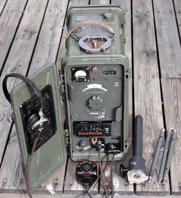
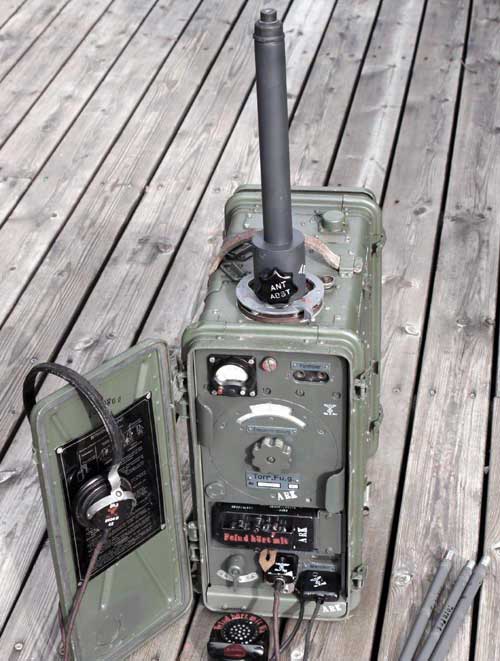
Finished Torn Fu.g project.
Here the Torn Fu. g completed with the test antenna.I make to types for the tests. Here is the repro of the original antenna-coil.
![]()
![]()
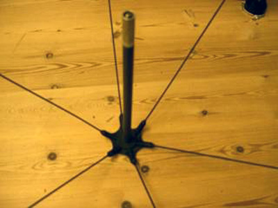
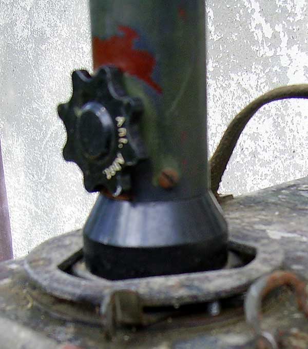
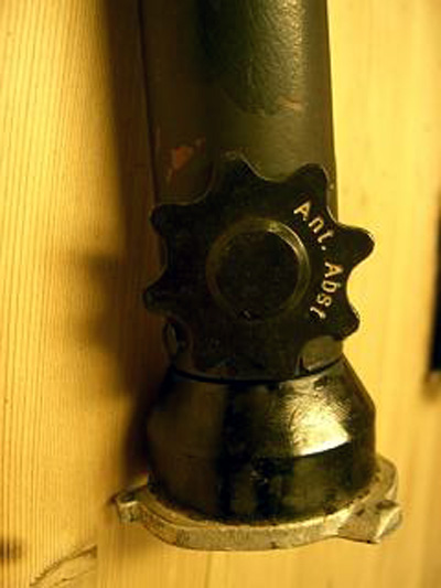
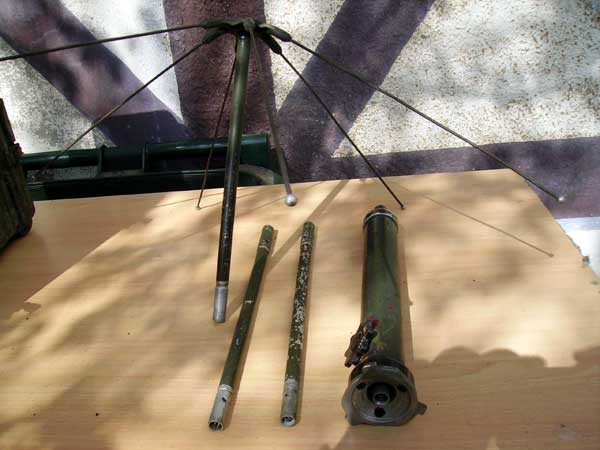
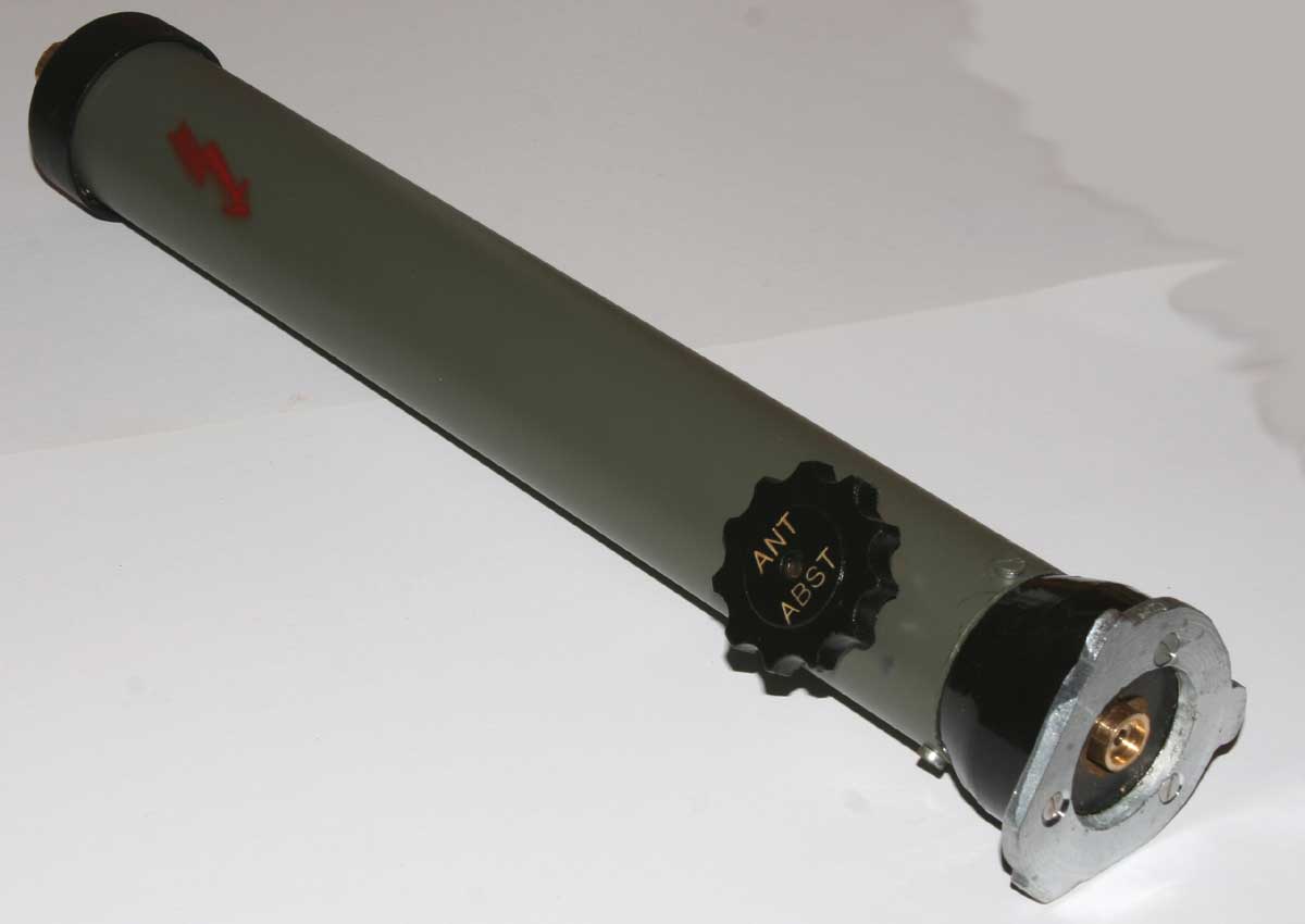
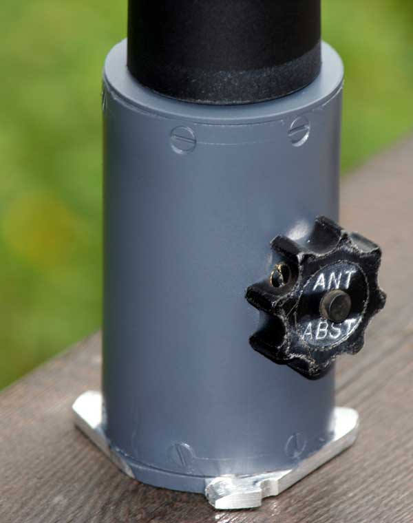
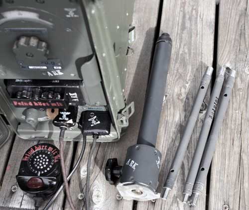
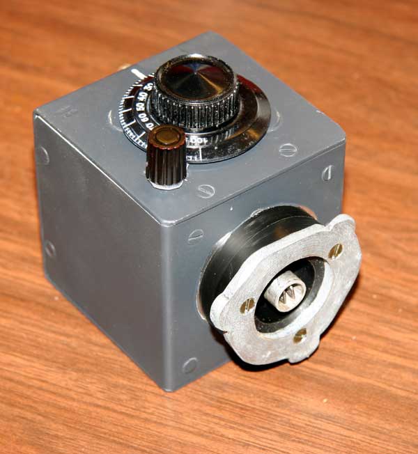
Longwire "Abstimmung" unit.
This unit was made for Tornfu.g to use longwire antennas for long distance. It is possible to tune antennas with a lenght of ca 3m to 18m. I have seen this one time, included in my fathers 2 Tornfu g he get from the German 1945 in Oslo. When I was 9 years old, I plying with the Tornfu.g in the woods. Some times ago I get a picture from Yuri Desyatnik, and I thinking of this unit. I made one for my Tornfu.g, after my remember,but not remember all details of the unit.When we played with the Tornfu.g I remember we do not get this unit to work at all, only the 1,5m paitchantenna. I hope anyone could help with identification of the unit? Investigations in factories making radio equipments in Germany 1938-1946, I do not finding anything about it. It is not included in the normal Tornfu.g packages.
I am testing the "tuner" and it work very fine in the field.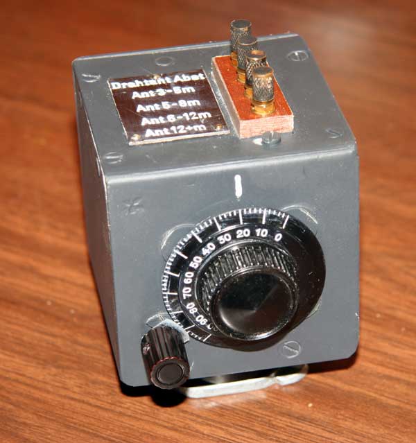
In the field with the radio on the back, it is importent to be two operators. The antenna coil is very sensitive,and if it is detuned, the radio do not work at all. It is sensitive for the hand capacity all around 15-20cm from the bottom to top af the antenna.It is impossible to tune the antenna on ground, and thereafter take it on the back.Second operator must adjust the coil when it on the back (max current adjustment), and somtimes retune the antenna when moving.On the ground operating all it mutch better,then you have "ground" connected to the radio.As seen on the instructions,it is 3 types of antennas working with the radio.Other antennas do not work, as longwire, dipol etc. The load impedance is ca 12ohm
 The Tornfu.g with 1,5m paitch-antenna , the AM
carrier signal was registered 130km away on a amateur receiver on daylight. Only
the weak carrier was registered, no mod.With CW
it could be communications.Not bad with 0.8 W output.With CW the output should
be ca 1.4w.Both the radios are working well as new. Both with
paitch-antenna,mic,earphone,antenna rods controll cable 60cm to controllbox and
earth 2x 3m cable.(Ruckenstutze) lower backrest and batteries.It was made a
little unit (box) to put on the antenna output on Tornfu.g,let it tuning
longwire antennas between ca 4m up to 16m. This unit are seen one time on a
German photo. Some told this was not a part of the Tornfu.g, but made from a
vehicle producer to adjust the radio to that vehicles antenna (a whip ca 3,5m)
on the back of the vehicle? I am hunting on it, but will try to make one
after the photo.
The Tornfu.g with 1,5m paitch-antenna , the AM
carrier signal was registered 130km away on a amateur receiver on daylight. Only
the weak carrier was registered, no mod.With CW
it could be communications.Not bad with 0.8 W output.With CW the output should
be ca 1.4w.Both the radios are working well as new. Both with
paitch-antenna,mic,earphone,antenna rods controll cable 60cm to controllbox and
earth 2x 3m cable.(Ruckenstutze) lower backrest and batteries.It was made a
little unit (box) to put on the antenna output on Tornfu.g,let it tuning
longwire antennas between ca 4m up to 16m. This unit are seen one time on a
German photo. Some told this was not a part of the Tornfu.g, but made from a
vehicle producer to adjust the radio to that vehicles antenna (a whip ca 3,5m)
on the back of the vehicle? I am hunting on it, but will try to make one
after the photo.
The variable capacitor (C4) oscillator values for the frequency adjustments.(Adjusting the plates).
| 3,500 Mhz 12 pf |
| 3,400 18 pf |
| 3,300 24 pf |
| 3,200 31 pf |
| 3,100 39 pf |
| 3,000 48 pf |
| 2,900 57 pf |
| 2,800 68 pf |
| 2,700 80 pf |
| 2,600 93 pf |
| 2,500 107 pf |
Test instruments for all restaurations work

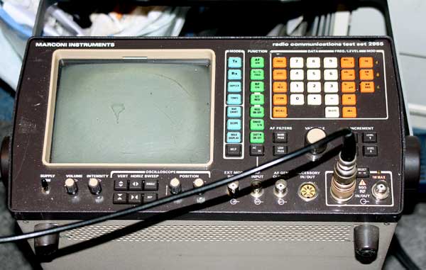
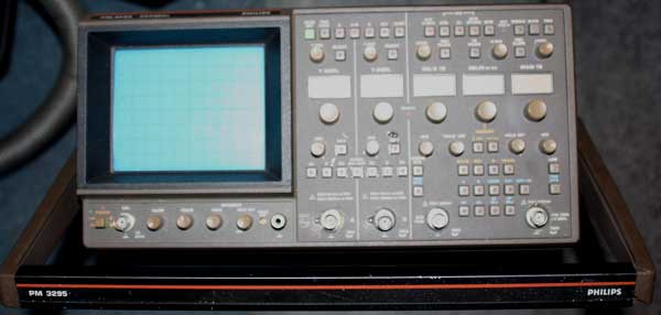


All round Marconi 0-900Mhz professional mobilradiotester. Philips dual 500Mhz Scope and Tektronix 1401 spectrumanalyzer.
 This site was last updated
05/16/18
Home
This site was last updated
05/16/18
Home


