 PRC-10a
PRC-10a
Manpack Military Radio
|
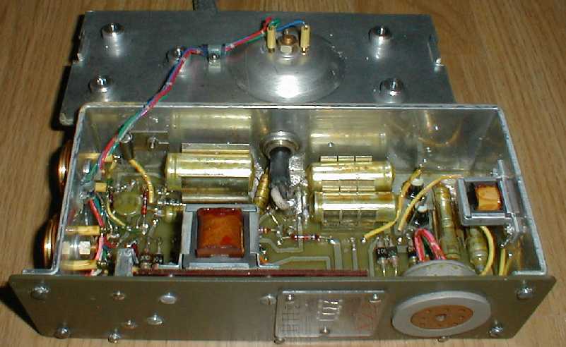
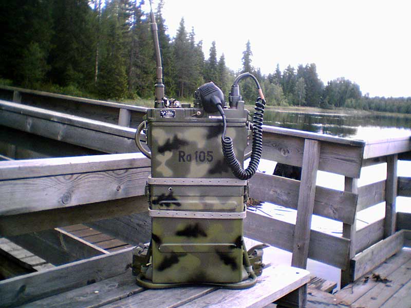
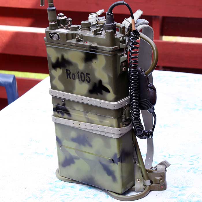
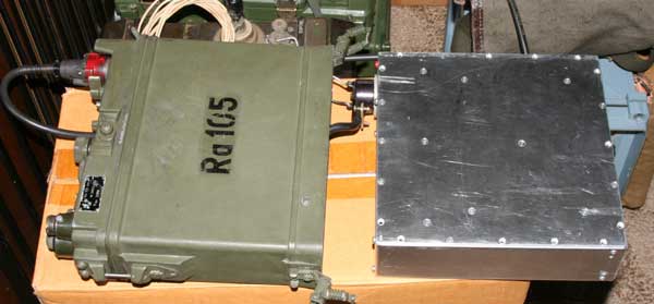
I have worked with this set in the field together with Russian R-105D and R-105M,and the frequence stability on Ra-105 (PRC-10a) is a looong way from the russian units stability.Russian and German Wehrmacht are built on the same chassis alloy constructions,giving perfect stability for self-oscillating oscillators.Ra-105 is made of alluminium plates giving vibrations and unstability,yes,but it works.
![]()
![]()
![]()

![]()
![]()
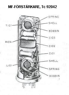
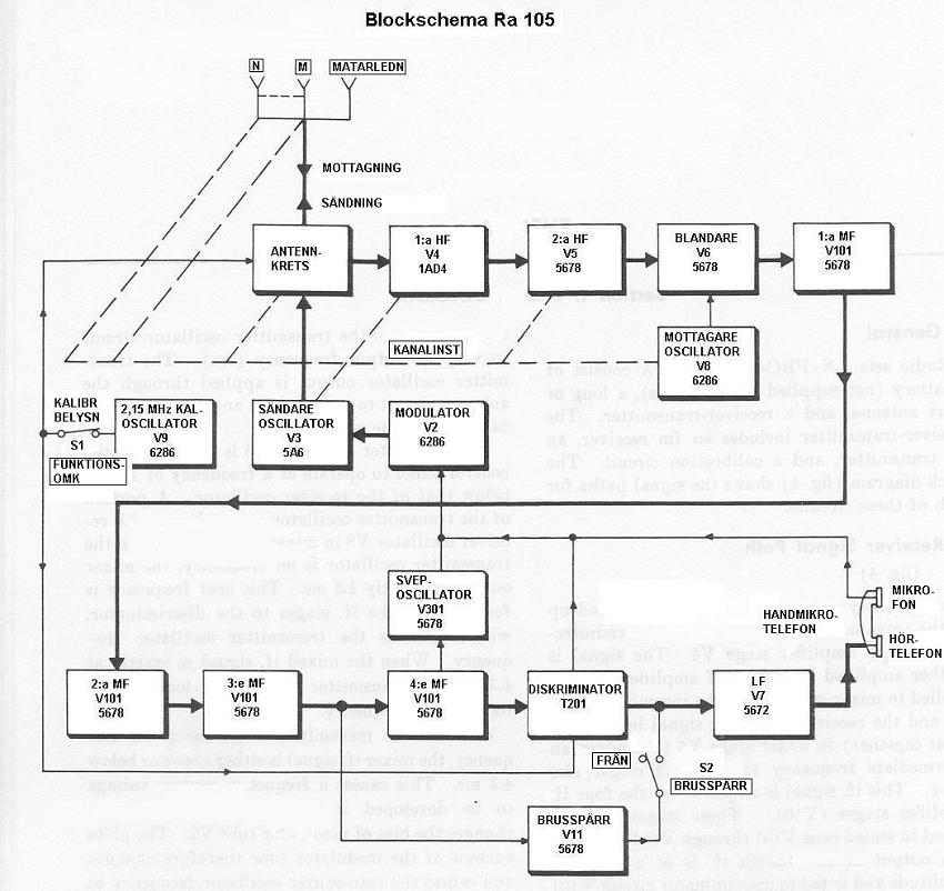
Technical data: Receiver: superheterodyn. IF- 4,3 MHz
The PRC-10 working time in the field ca 25 hrs RX with 1:5 TX
| Transmitter mod. | thelefony (FM) |
| Antenna power | ca 0,9 W |
| Antennas | - Normalantenna |
| - Marschantenna | |
| - koaxialcontact for connecting stationary antenne | |
| Frequencies | 38 - 55 MHz Cover 6m amateur band FM |
| Channel spacing | 100 kHz |
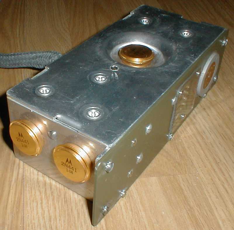
| Valves | 14 st subminiatyr-valve |
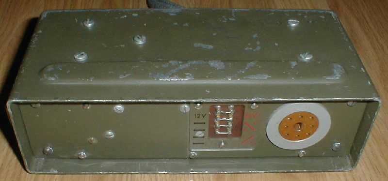
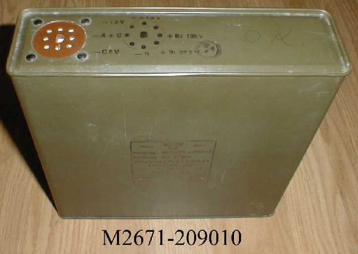
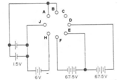
| Power input | - Battery with connections for +135 V, +67,5 V, -6 V och +1,5 V |
| - 12/24 V converter | |
| Weight | Totalt 7.8 kg, where battery 3,2 kg |
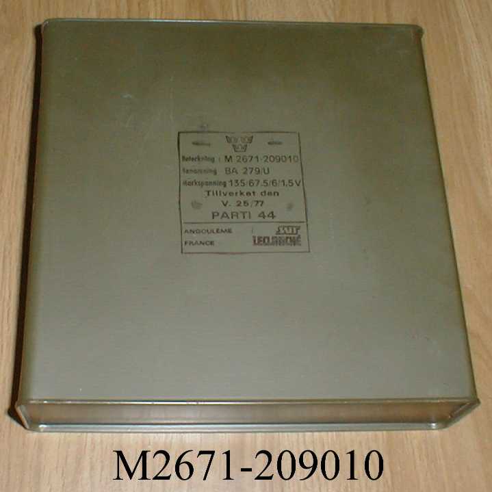
| Producer Factory | Svenska Radio Aktiebolaget (SRA) (license) |
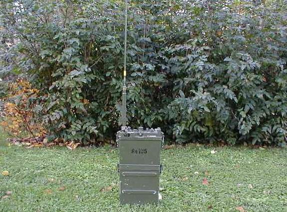
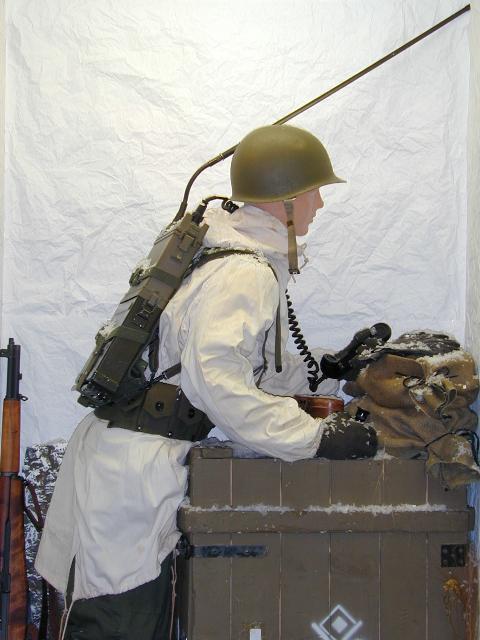
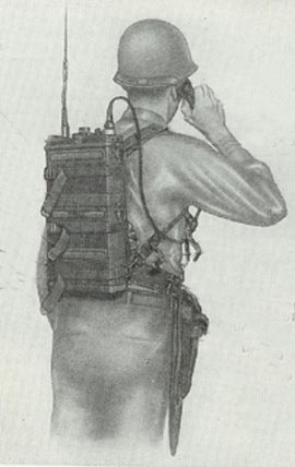
The AN/PRC-10 came into the Army inventory in March, 1951. It is a 16 tube FM radio which was used as a squad radio. It is part of a family of radios AN/PRC-8, AN/PRC-9, and AN/PRC-10 which differ only in the frequency of operation and the components that determine that frequency.
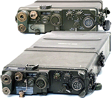
Each radio set consists of a superheterodyne FM receiver and FM transmitter use a common antenna. The Receiver-Transmitter consists of a single panel chassis assembly mounted in a magnesium case with a watertight seal. A short eight wire cable connects the chassis to the BA-279/U battery while two springs clamps hold the R-T case to the battery case. The PRC-8,9,10 radios can be adapted for vehicluar use by means of the AM-598/U Amplifier Power Supply that converts 24 volts to the operating voltages of the radio (the battery cable plugs into the power supply), plus can drive an audio aux speaker.
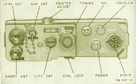
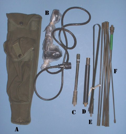
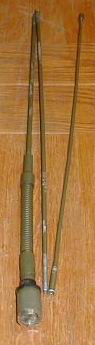
The AT-271/PRC antenna (the long antenna) is used with the radio for maximum range. It is provided in seven sections connected by an internal stainless steel cable, a total of 10 feet long. When folded, the cable keeps the sections together as a group. This antenna screws into the LONG ANT jack on the top control panel. The AT-272/PRC antenna (the short antenna) consists of several lengths of flexible steel tape riveted together, making a tapered antenna 3 feet long that screws into the SHORT ANT jack. The short antenna is for general service and can be folded into the carrying bag that is part of the PRC-10 equipment list.
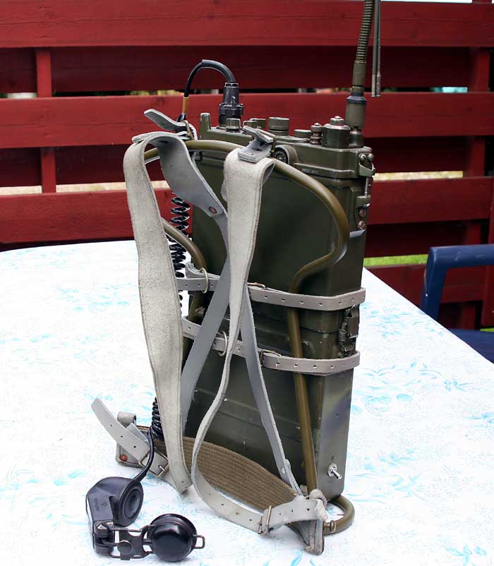
In the field, soldiers quickly found that the backpack antenna was a sniper target. The antenna was therefore removed, or sometimes the radio was carrid upside down with the short antenna pointed to the ground, which did not seem to effect the range of 3 to 12 miles, depending on antenna used and siting conditions.
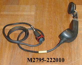
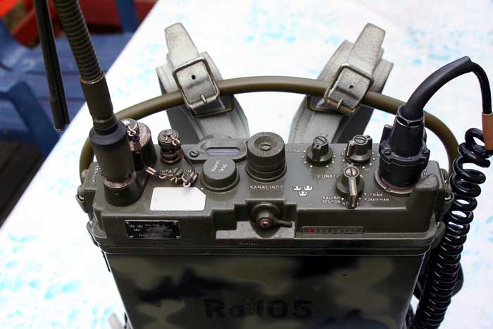
The handset H-33B/PT connects through a cable and ten contact plug that connects to the AUDIO jack on the control panel.
The Army divided up the radio spectrum into three bands, Armor, Artillery and Infantry. The PRC-8 20-27.9 MHz, the PRC-9 27-38.9 MHz and the PRC-10 38-54.9 MHz. Note there is a small overlap for inter-division communication. The 38.0 to 54.9 MHz band was what we now call squad radio


JAN Type: AN/PRC-10
Nomenclature: Radio Set
Reference: TM 11-5820-292-XX
NSN: 5820-00-223-5122
Components: RT-176/PRC-10 Receiver-Transmitter, CY-744(*) Battery Case,
BA-279/U Battery, AT-271(*)/PRC Antenna, AT-272(*)/PRC Antenna, AB-129/U Antenna
Spring, H-33(*)/PT Handset
Weight: 7.8kg
Mode: 30F3
Frequency Range: 38-55 MHz
Power Input: A: 1.5, B1: 67.5, B2: 135, C: 6 V from BA-279/U
Power Output: 0.9 W
Number of Channels: Continuous Tuning (Calibration Osc at 2.15 MHz
points)
Replaced By: PRC-25
Replaces: BC-1000
Part of: PRC-10
Antenna: AT-271 and AT-272
Description: The PRC-10 is a portable, low-power, frequency-modulated
radio set which can be pack-mounted or installed in vehicles to provide voice
commumnications over relatively short distances. They can also be used for
homing. Provision is made for remote operation and unattended relay operation.
Source: TM 11-5820-292-10, 12 Sep 61. PRC-10a,transmitting and
receive in 6m (50-54Mhz) amateur-band FM only,and therfore usable to this work.
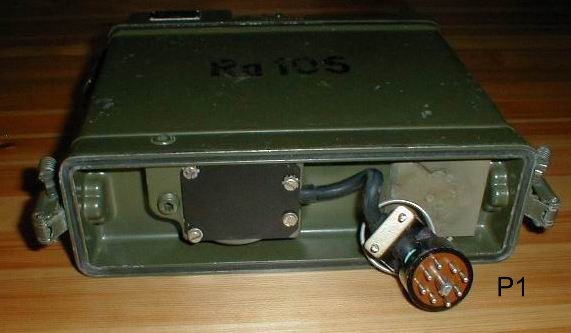
Battery-contact P1
|

![]() Partslist and
Doc
Partslist and
Doc
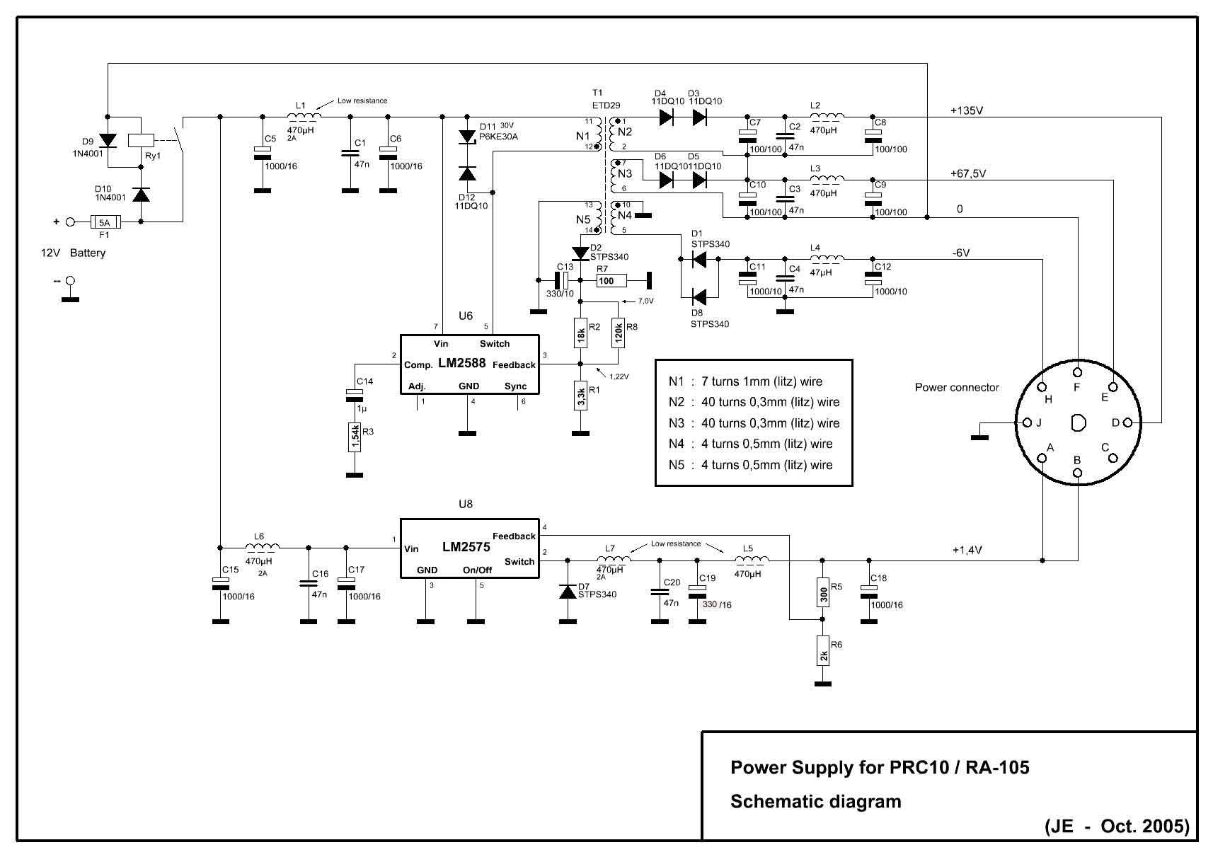
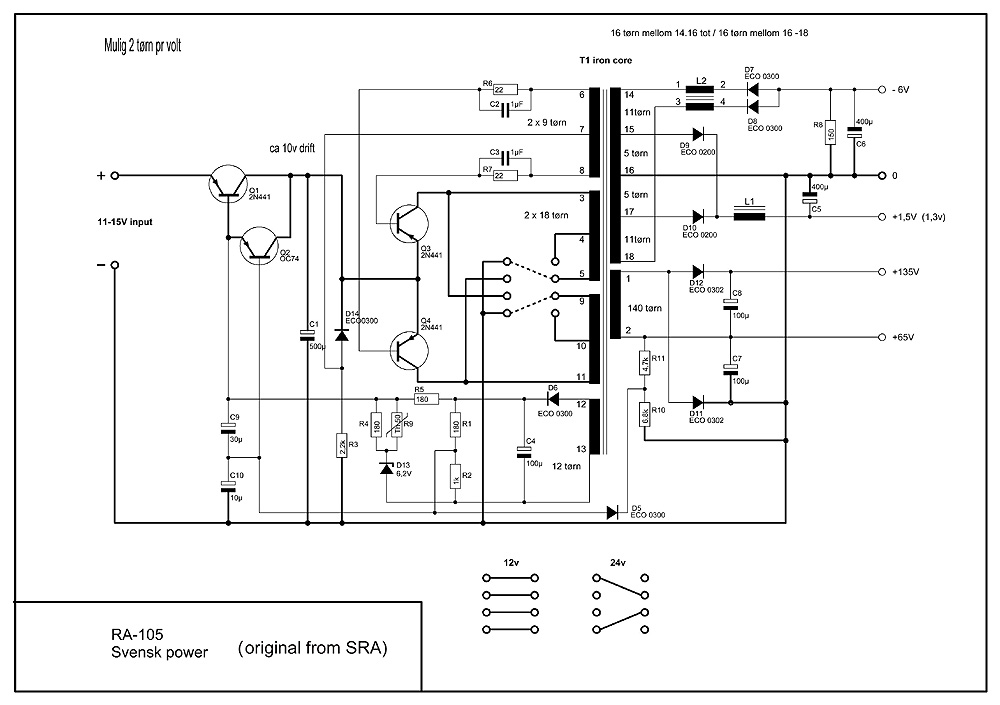 SRA made the power for the Swedish army.
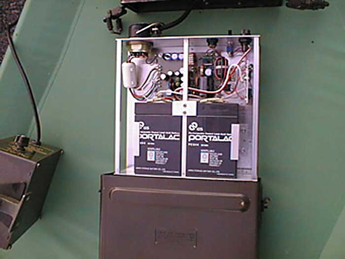
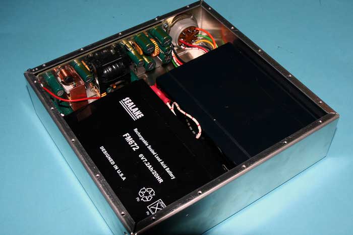
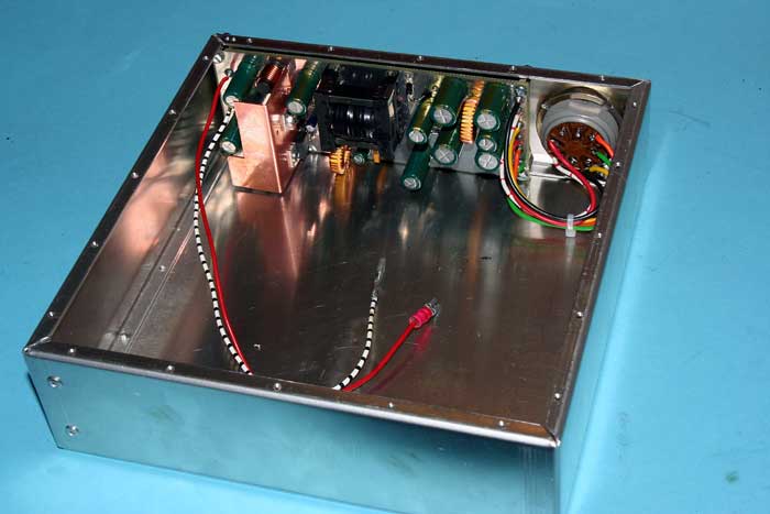
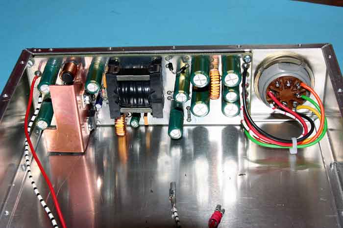
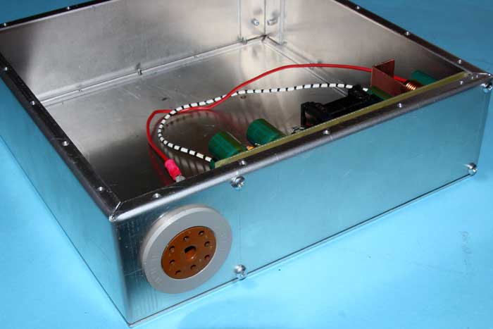
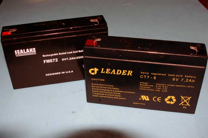
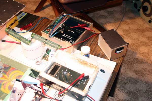
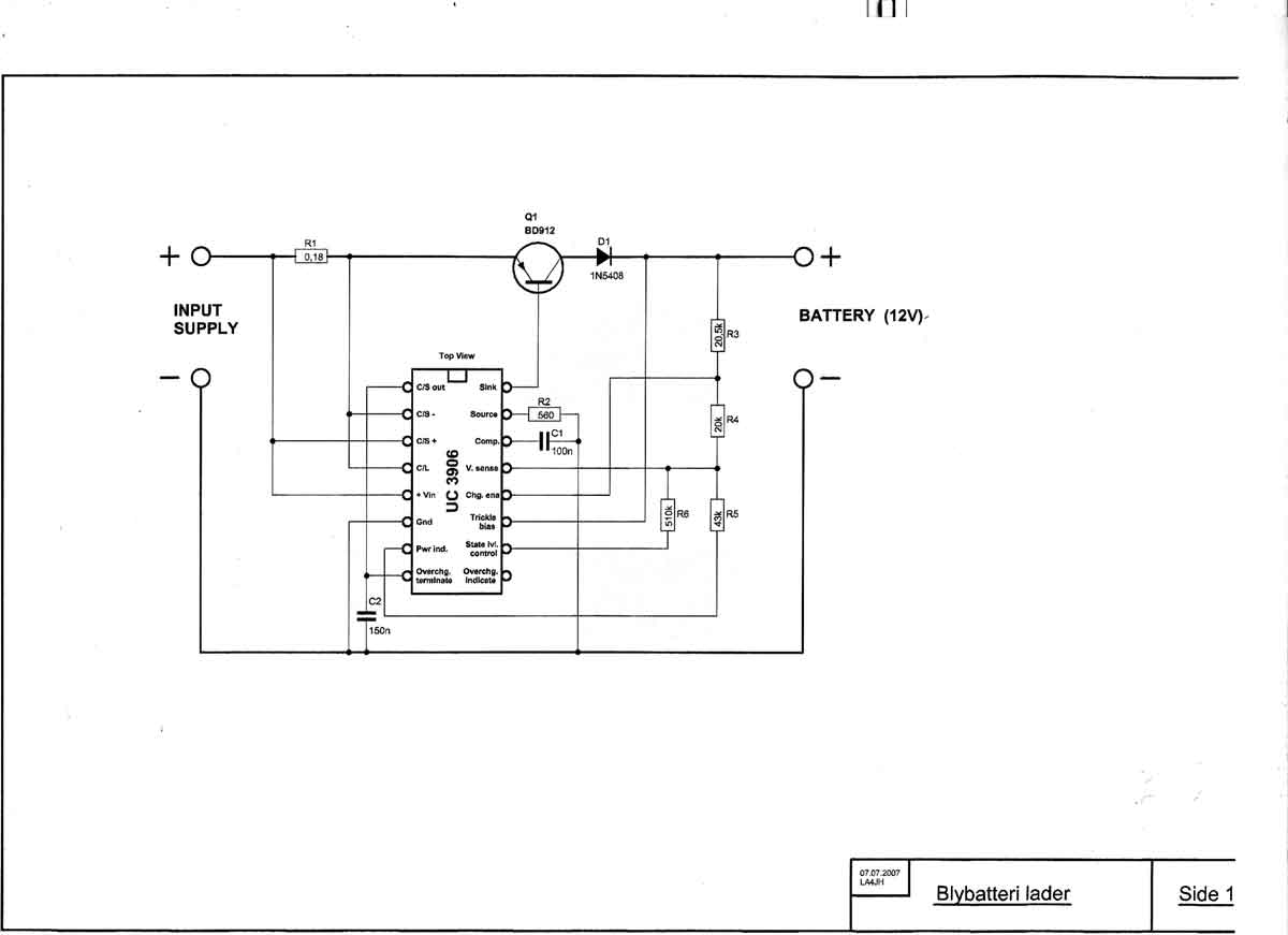
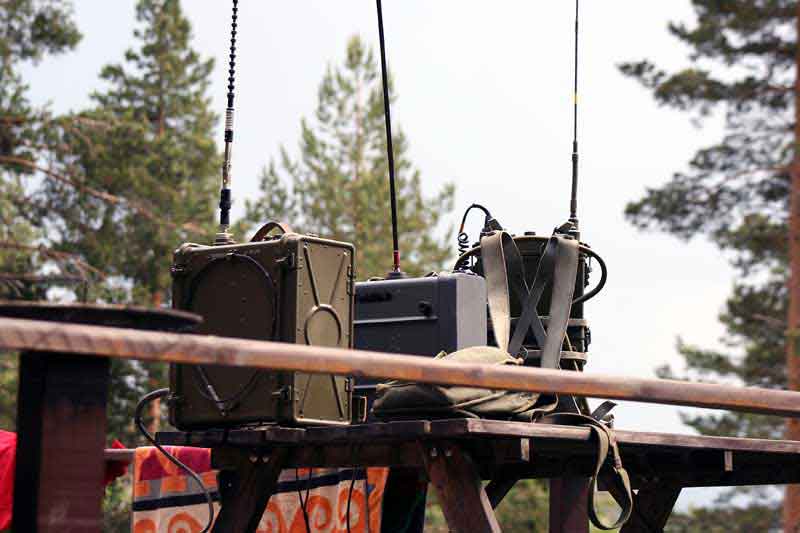
The radio RA-105 (PRC-10) going on air. All the voltages to the radio as spec. As a problem with charging correct the Gel Battrys ,we constructed a charger for this type. This controll all the charging and after charging.The components came from the Web page ELFA
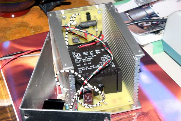
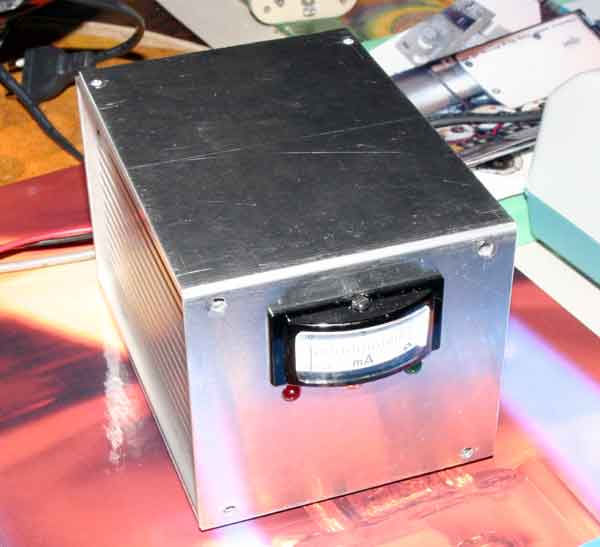
I constructing a new power modul for PRC-10 (RA-105).The unit take place into the old battery box.Two 6v-7.2Ah chargable battery pack included, make all the voltages needed for operations.This making it possible to operate the radios we have.The orginal pattery pack with dry cells is not more possible to get.As the radios working on amateur 6m band (50-52Mhz) it is interesting to have them to work again.The project is now finished.The converter functions as it should,and the RA-105 going on air.

36. Correction of Defect in Socket of
Battery BA-279/U
Note. The procedures below apply to Battery BA-279/U procured on Orders No.
16613-Phila-51, 16517-Phila-51,
14453-Phila-51, and .15609-Phila-51 .
a. Reason for Failure of Radio Sets AN I PRC-8, 9, and -10.
Reports have indicated operational failure because of intermittent or poor
contact between@battery plug P1
and the socket of Battery BA-279/U.
Investigation discloses that the following factors are primarily responsible for
such difficulties.
( 1) The jacket socket opening is too small to allow the
battery plug to be seated properly in the socket.
(2) The battery socket has sufficient give under pressure to prevent
proper mating@because of inadequate support in the
socket well.
b. Corrective Action in Production.
These difficulties have been corrected in production on contracts awarded after
21 December 1951 by increasing the diamet r of the jacket socket opening from
1/4 inches to 3/3 inches and by providing improved support in the battery
socket well.
c. Corrective Action in Field.
Application of either of the following measures will insure proper mating
between the plug and the connector, whether or not the battery socket is
supported adequately in the socket well:
(1) With a knife or@other suitable instrument, cut the top of the battery
jacket, at the socket end, free from the sides for a depth of 2 inches to permit
that portion of the jacket to be folded back from the socket.
(2) Increase the size of the jacket socket opening to approximately 13A inches
in diameter by trimming away a portion of the periphery of the jacket socket
opening.
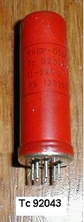
Tube Failure.
An undetermined quantity of tubes type 1AD4, manufactured by Ratheon, have a
useful life of as little as 10 hours when used as the receiver oscillator (V8)
in Radio Sets AN/PRC 8 and AN/PRC-10.
These tubes are in lot numbers 202 through 226.
Failure of this tube is evidenced by oscillation, interrupted at a low
repetition rate resembling motor-boating.
This type of failure will not be indicated on a tube tester.
Present available information indicates that this phenomenon is the result of
grid contamination occasioned by an improper aging processing during
manufacture.
b. Replacement.
If oscillation of this type occurs, remove the original tube and replace it with
a new tube (Sig C stock No. 2J1AD4).
When replacing this tube, be sure that the red dot on the tube corresponds to
the pimple on the socket.


This site was last updated 10/09/15 Home