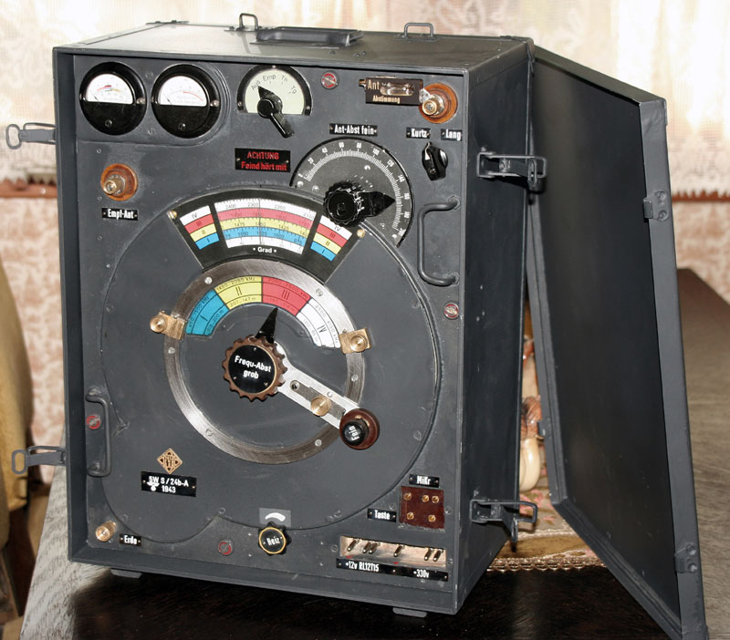
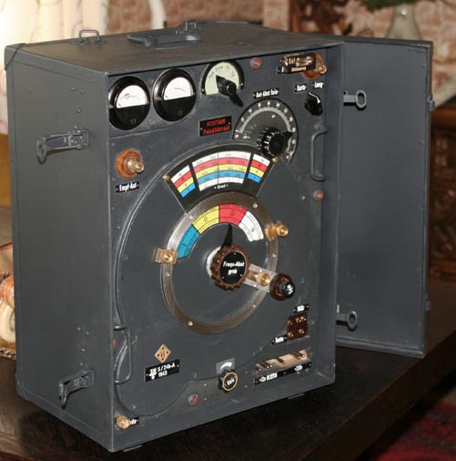
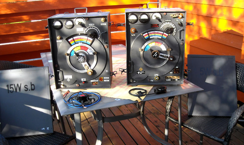
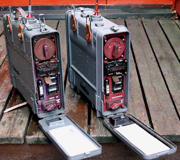
5w s.b Wehrmacht sender. 1st project.


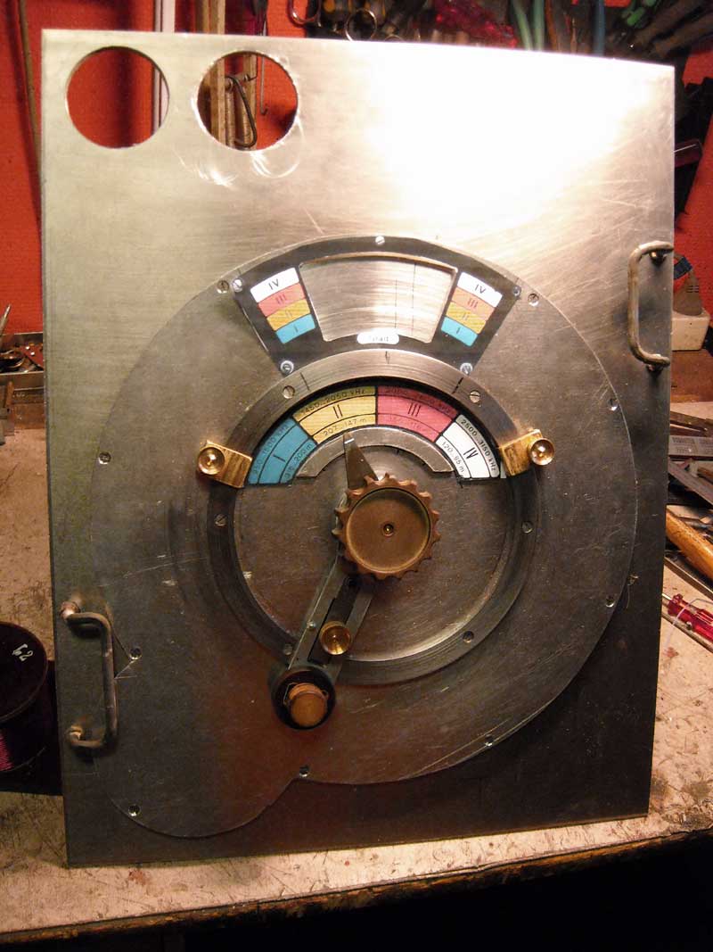
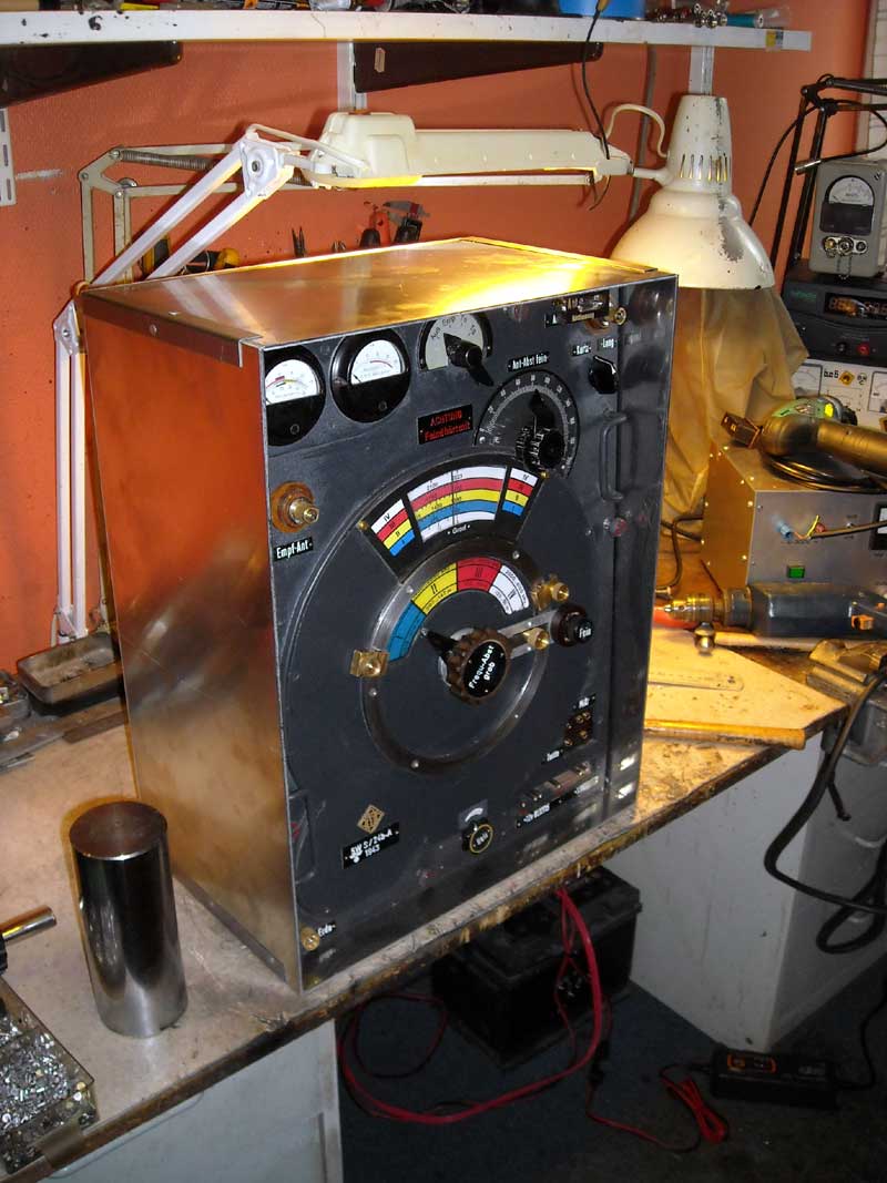
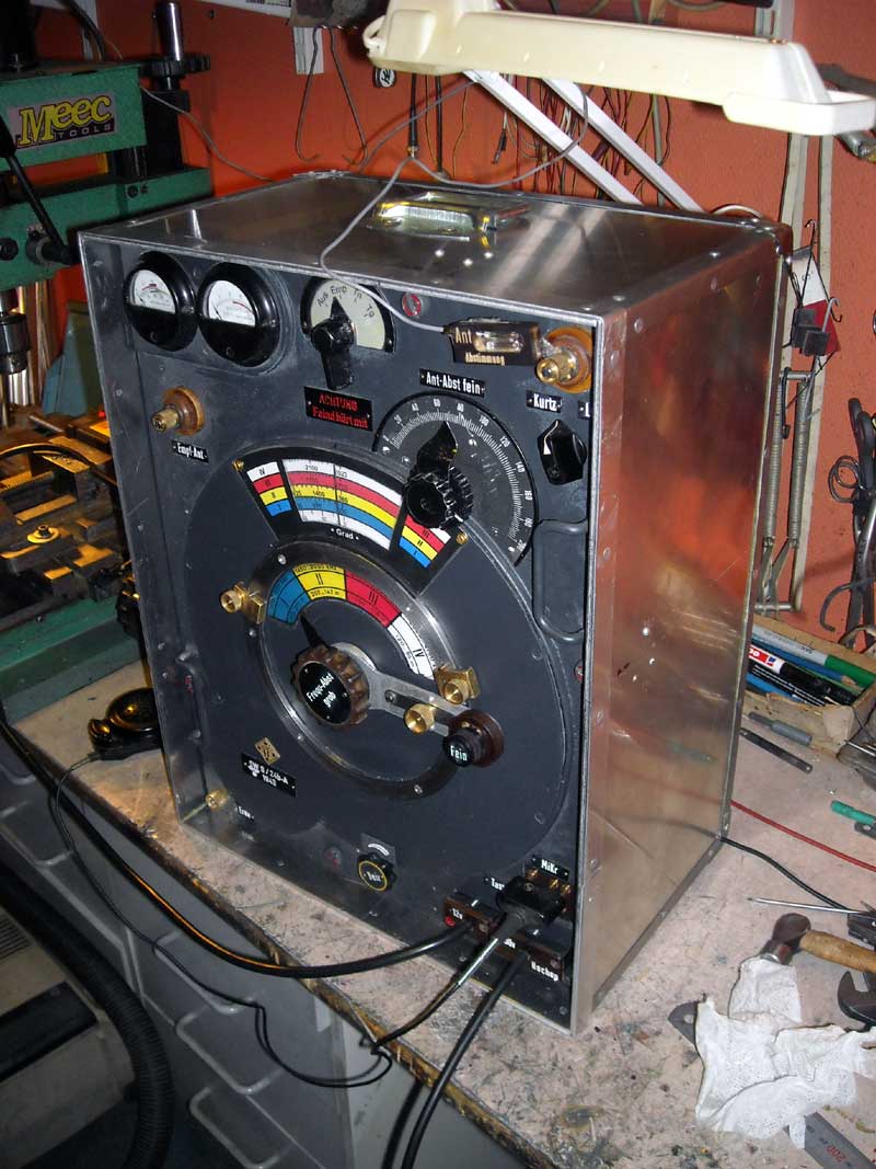
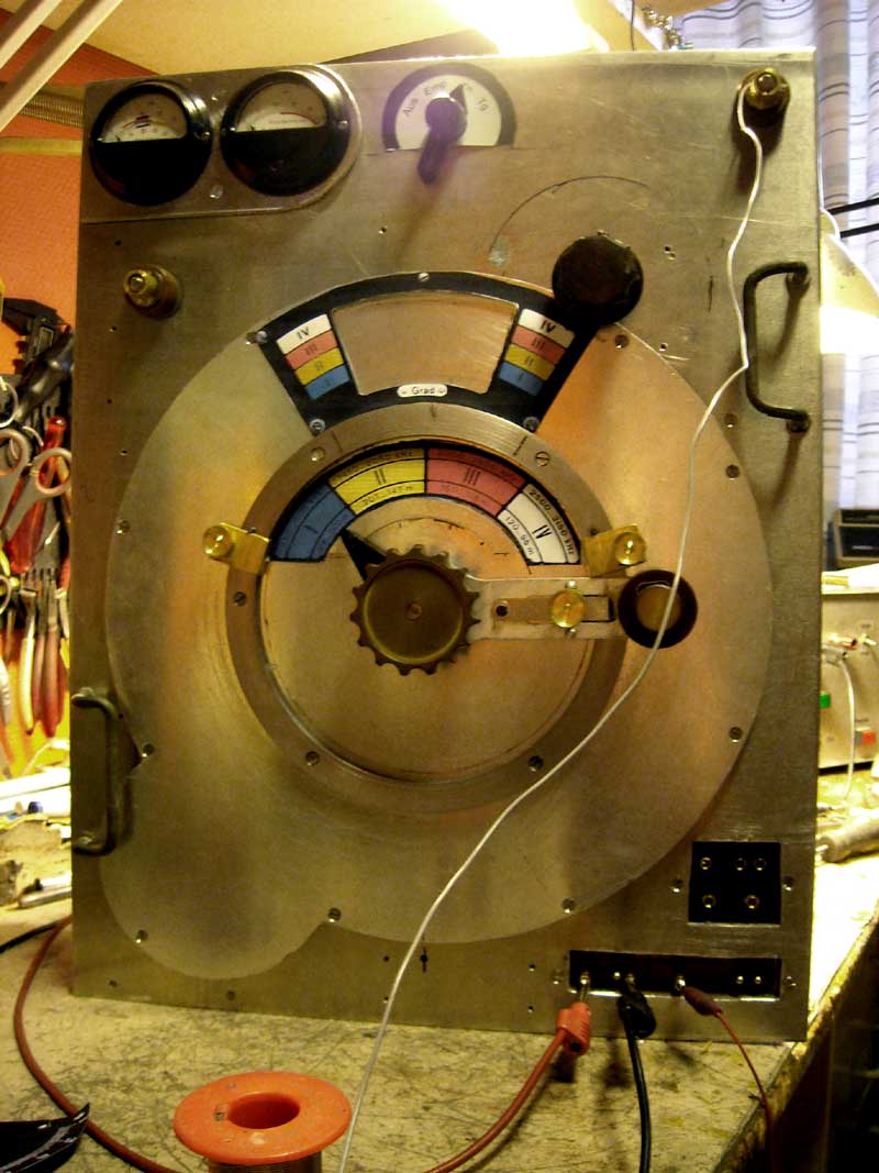

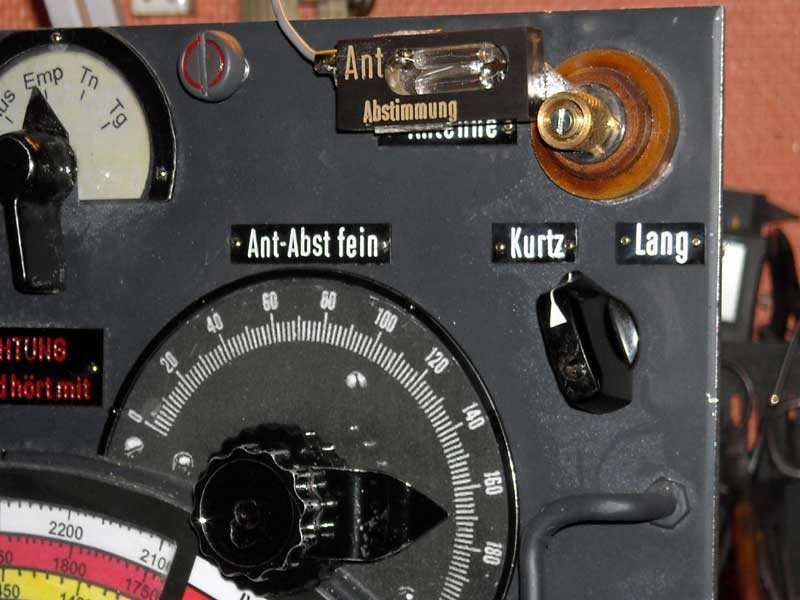
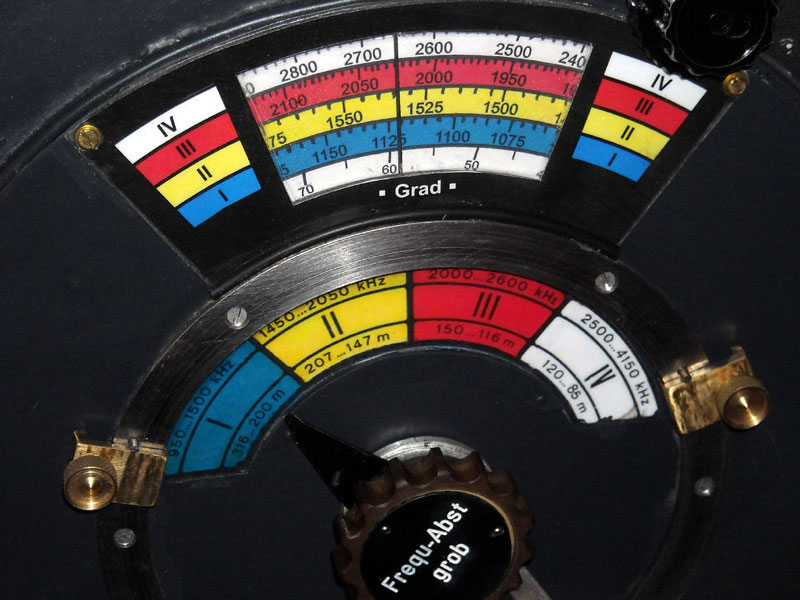
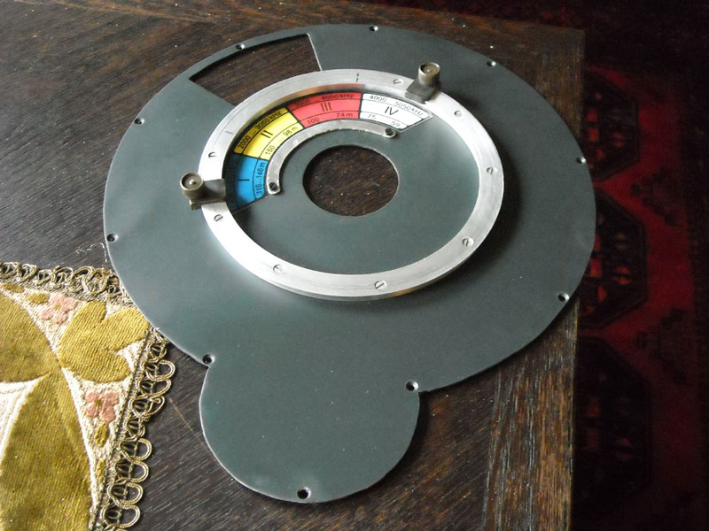
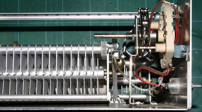
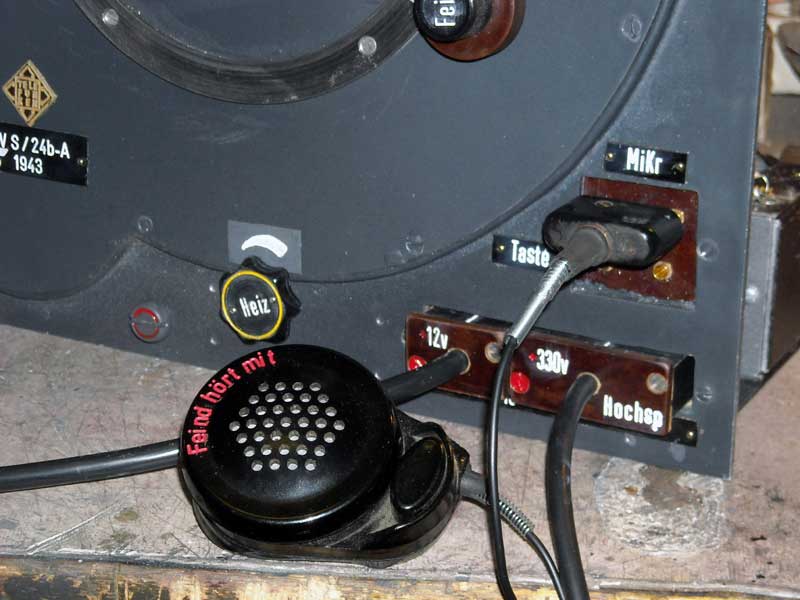
Constructing a Wehrmacht 5w sender with a better antenna usement. The RS241 changed with more modern tube RL12T15 with 12v heathing and catode. The "Umfomer U5a1" some modefication to give 12v direct to the sender tubes. Bypassing the resistor adjusting RS241 filament to ca 4-5volt. A feedback wire from the sender through the 12v wire start and stopp the Ua51 when the switch going from Receive to Tg or Tn. The main switch " Aus" all filament and activity stopped" "Empfanger" only 12v filament standby (ca 1A)" and Tg ,Tn U5a1 starting. Modefications for the variable antenna condensator,via a exstra tunig wheel inside the main atenna adjustingwheel. Originally this condensator tuning together with antenna adjusting rod. It is doing for more easy antenna tuning,but it is not a reel good methode for different lenght of antenna wires. The little unit on ANT output, it is a tuning lamp, a controlling unit together with the Ma meter for test. The frequency band 4 normally from 2500kc 3150kc are changed to endfreq 3,80kc covering 8om amateurband.
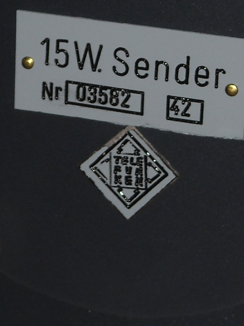
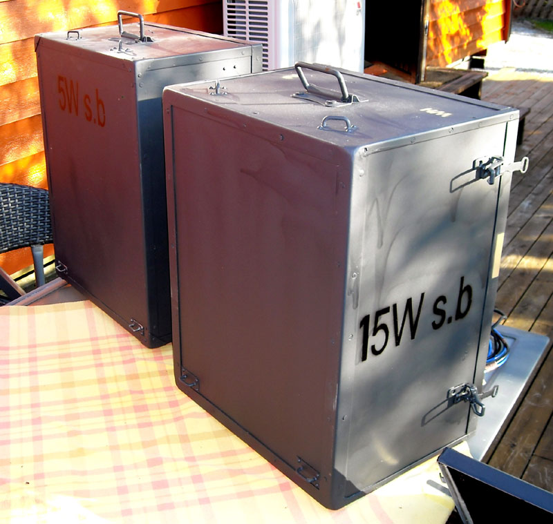
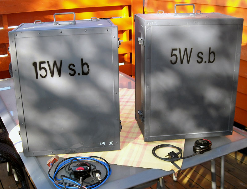
15w sender DDS controlled. 2nd project.
15w DDS transistor/computer controlled 5w s.b ordinary originally electrical constructed
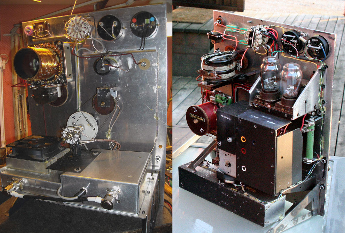
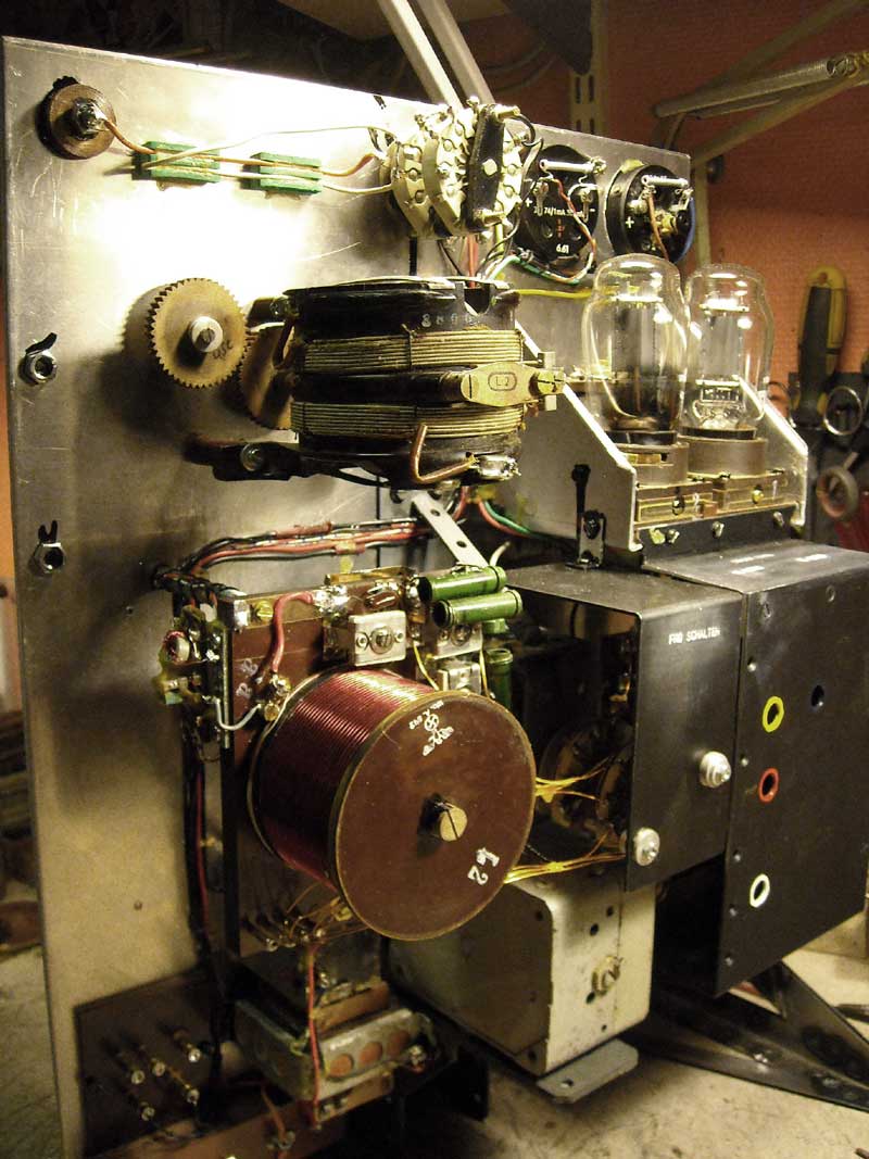
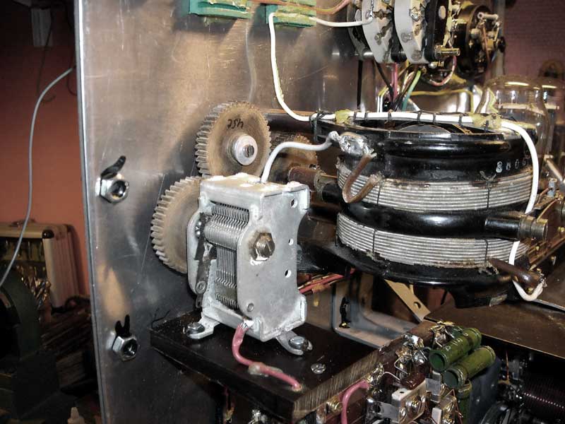
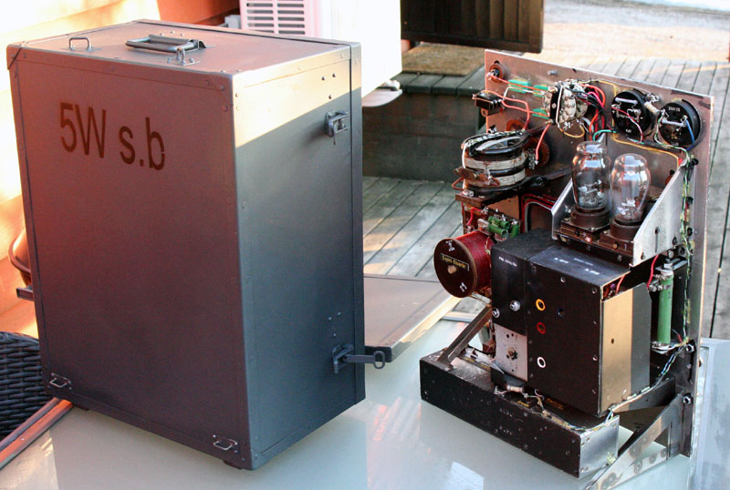
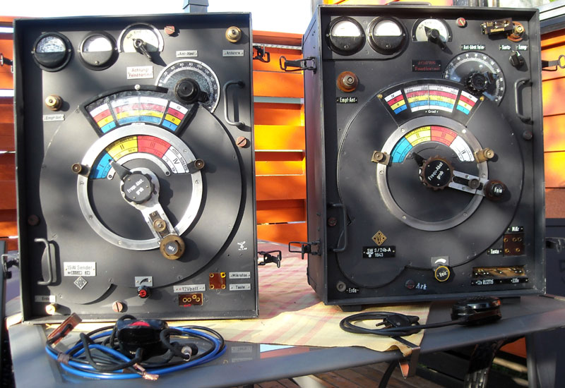
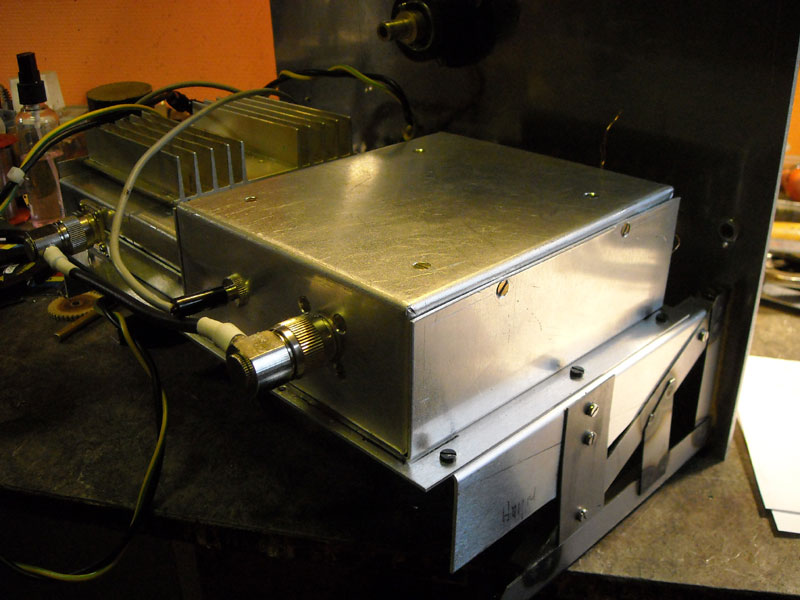
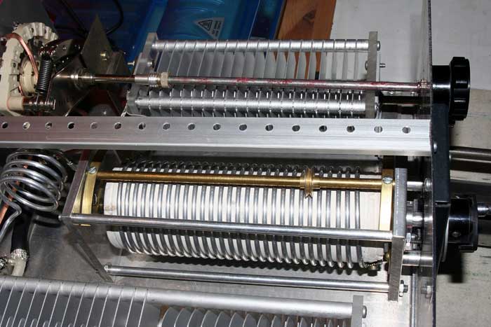
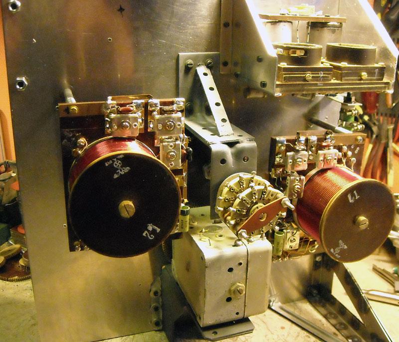
The 15w DDS transmitter have few components. As seen,it is a antenna tuner coil 600uH with 32 taps on the coil via the switch and 470pf variable cond to earth on antenna output. Band switch,DDS /driver unit and a 2 power transistors unit, with a big fan. Frequency adjustment going via a wire wheel to a 20k precision pot-meter. Stability +/-10hz. All needed to power the transmitter,only 11-15vdc and ca 3,5A. Modulations made in the DDS unit,as 85% AM with AGC. Right picture a 5w s.b constructed right after the original drawing. Only the modulator in the bottom giving reel AM modulation. This is anodemodulation on the tube-plate via a transformer.The grid modulation reduce some power output from the PA tube. 5w.s.b use a 450uH variometer to antenna. The DDS transmitter giving 15w output and antenna matching wires from 4m to 18m. The frequency on the DDS unit cover from 950kc to 5Mhz. The PA is a broadband amplifier. The 5ws.b 950kc to 4,150Mhz to cover the 80m amateurband to.


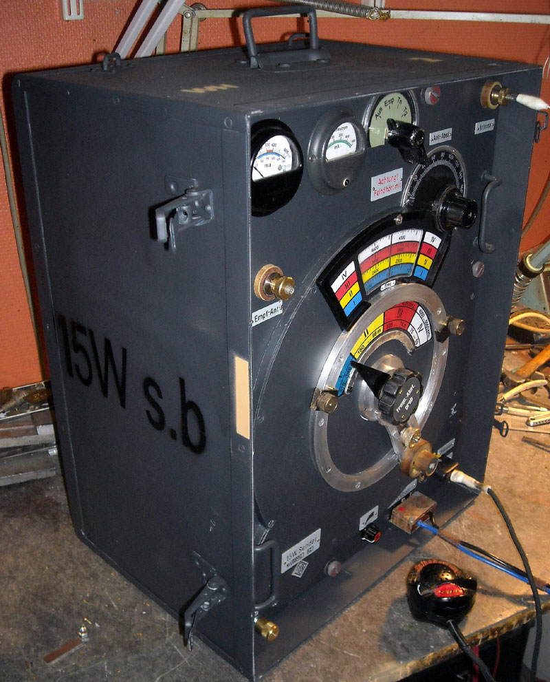
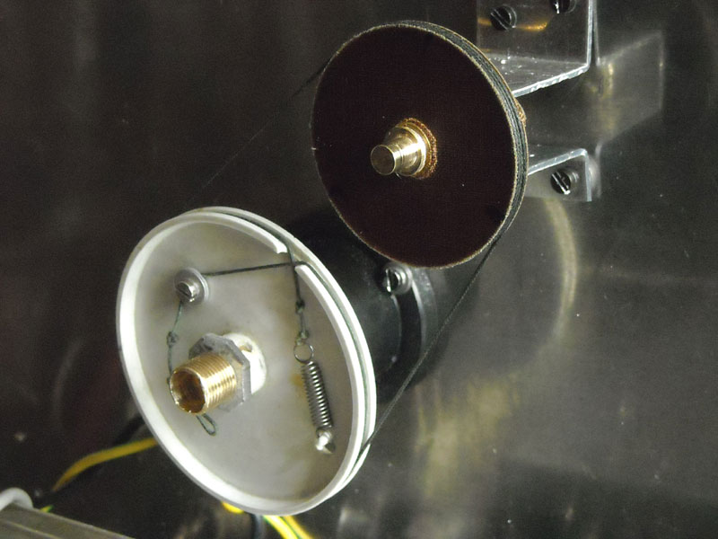

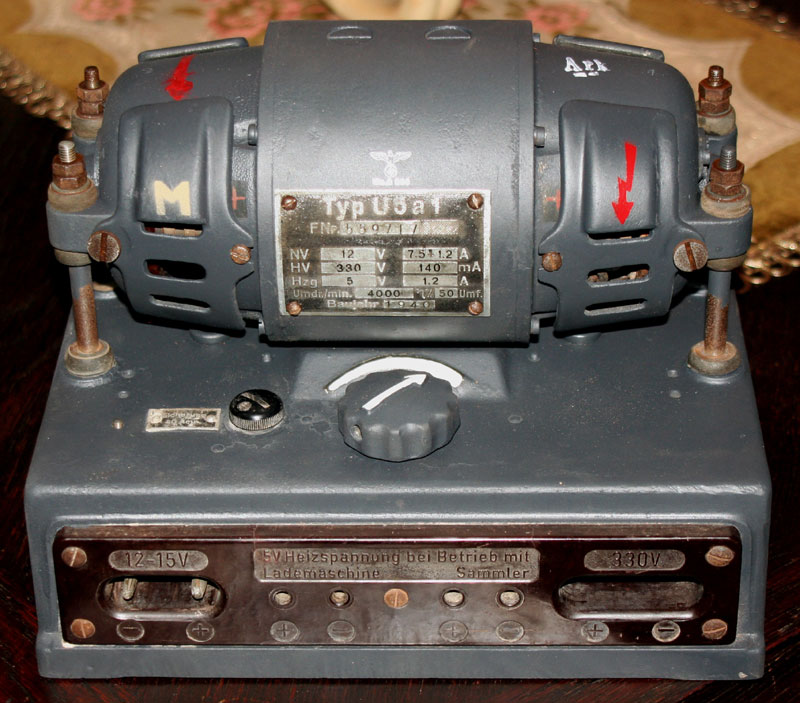
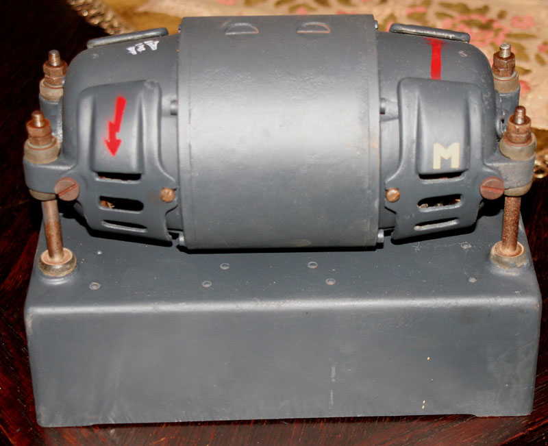

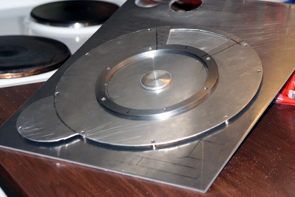
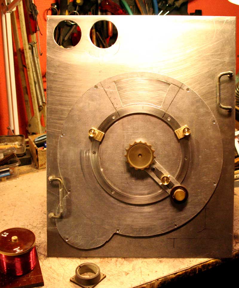
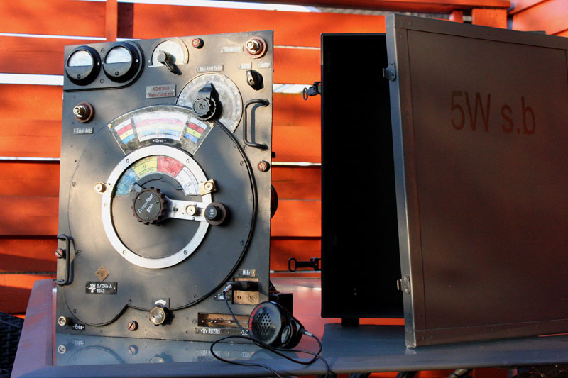
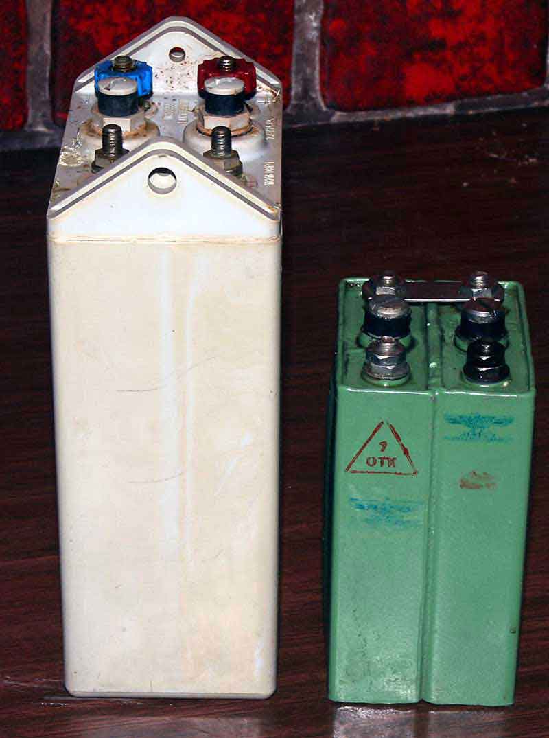
The 5w s.b transmitter use U5a1 rotating generator. The main data 330vdc at 140ma. I have never on this one,or other get more than ca 285vdc at 110ma and 12,4v batt supply. I have demounted every part of the unit,changed with new SKF rollers etc etc. With 13v batt it giving 312vdc 110ma. Therefore I have mounted a switchmode unit inside the generator. 2 modefications only. It giving stable 335vdc +/-5volt between 250-380v. When I use the 5ws.b it is no noise from the generator,it is not rotating. So, I controll the starting switchmode through the relay starting the supply to generator. The RS241 tubes used in 5w s.b I changed them to RL12T15. More modern tube for the war than RS241 from 1930. Filament 12,6v and cathode. Wok better together with 12v battery power. It is funny to work with both of them, in the field. The switchmode unit could be mounted inside the 5w s.b box, but I do this for the cosmetics effect.
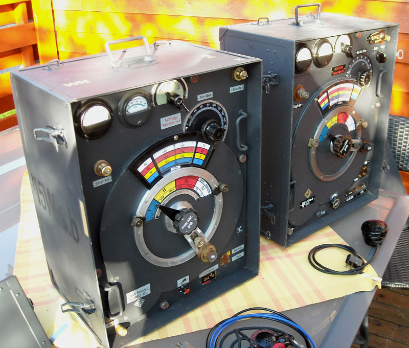
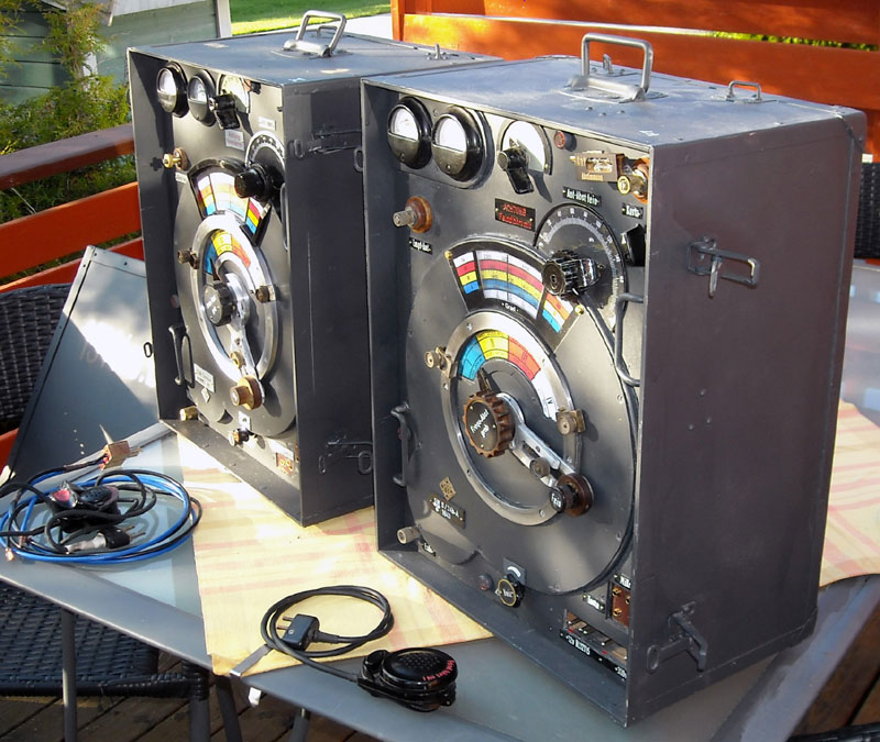
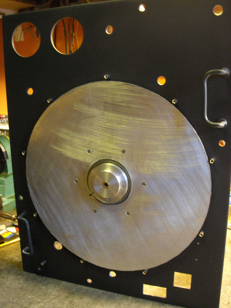
The 15w Sender, DDS and microcontroller,controlling a 3 step broadband amplifier giving ca 20mw, then PA amplifier broadband with 2 pushpull transistors, giving ca 15w output to 52ohm load. From this load it is a 10cm dia coil, ca 600uH with 32 taps to a switch to antenna, and a variable cond 470pf to ground. I use the units in reenactor amusements. The receivers are for the time a Sailor and a Torn E.b.
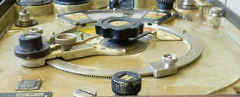
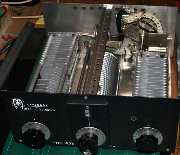
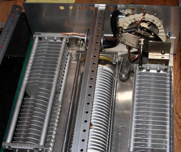
UT-2000a made from MURCH Electronics USA
Antenna tuner 2Kw, mod for bypass antenne.( Not delivered with bypass from factory)
'

.jpg)
.jpg)
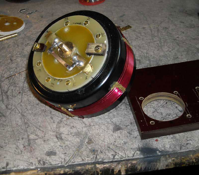
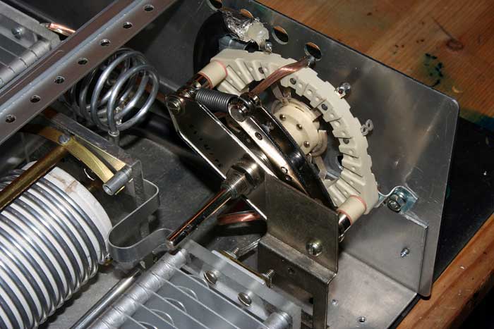
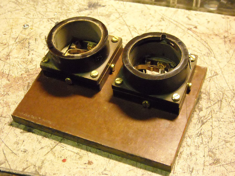
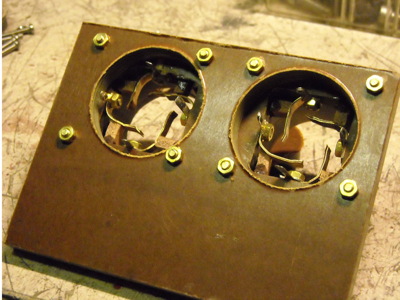
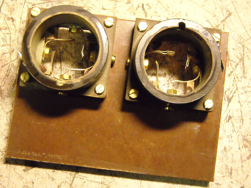
The drum for the moving coil,as I thought,was not made of ceramic. The coil is winded on a form, seems made of a sort of chalk with glue on outer side on a core,ca 10mm thick. The core is made of a sort of isolating matrials,backelite type. On each end it is a 8mm brass rod pressed into each ends. Both isolated. One end going to ground through a brass screw and end of coil.Because the weaknes of chalk matrial the press on the screw and coil end loosen, and if high power, from ca 400w and up,it will flame/burn HF between the coil end and the screw. The screw going through the coil end eye through the chalh lyer and into the brass rod through the ground.
The mod here is made of a new longer brass screw. The screw now going through the coil eye, and here a nut,and down into the brass rod. Tighten the screw.Now tighten the nut. (This is some "diffy" to do the last). The upper "Warm" end of the coil have the same problem. Next time to Fredrichafen I get a ceramic coil form.
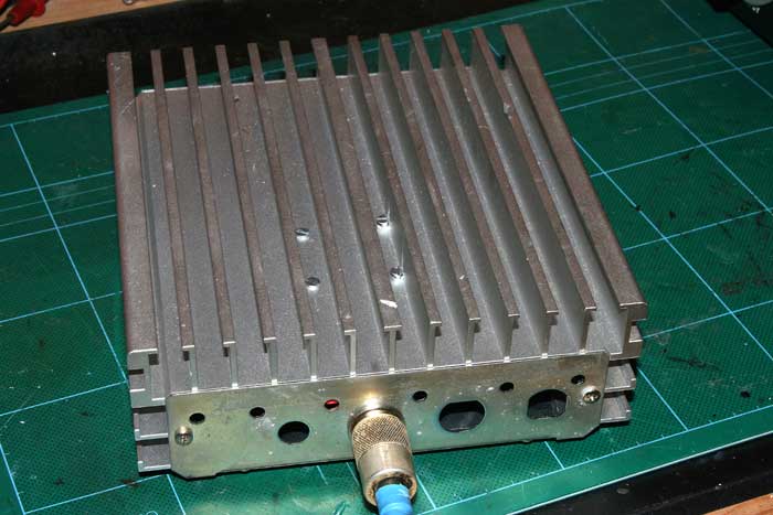
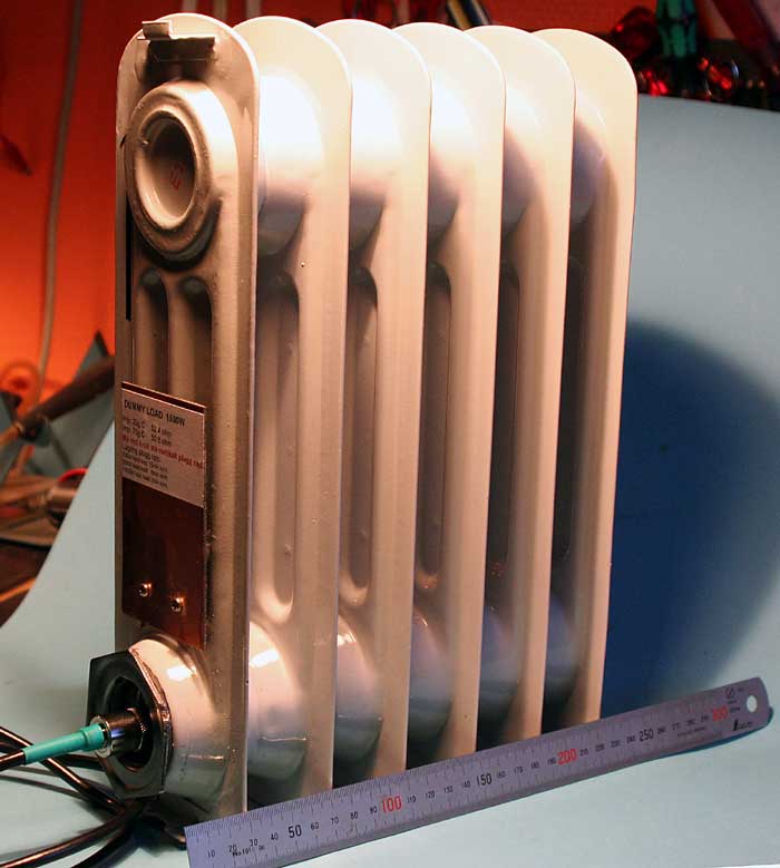
Dummyload 2-500Mhz 52ohm 100W kont, 200w 2min .


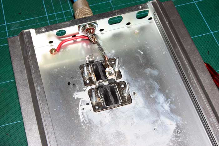
2 X resitors,each, 200w 100 ohm thin-film non resestiv type. First monted on a copper plate and then to the cooling surface. This do not work well, as the heath could not transform to the alluminium surface speedy enough. Possible the copper surface was unequal.Another problem was, after my uponion,that the thinfilm substrate on a thin wafer beryllium oxid, break through if you screw the settings screws to tight if the surface if not absolute plane. (If to mutch heath paste). Interesting page
Now it works fine,but it is better to have 4 resistors a 200 ohm to work for 800w. They are exspensives, about Euro 15 each.It is importent that all resistors connected as a "Star" for correct power to all 4. Working with a fan for cooling.
Bird Slug Model 43 Orginal 250H- 250w 2-30Mhz

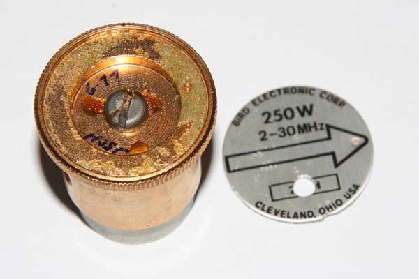
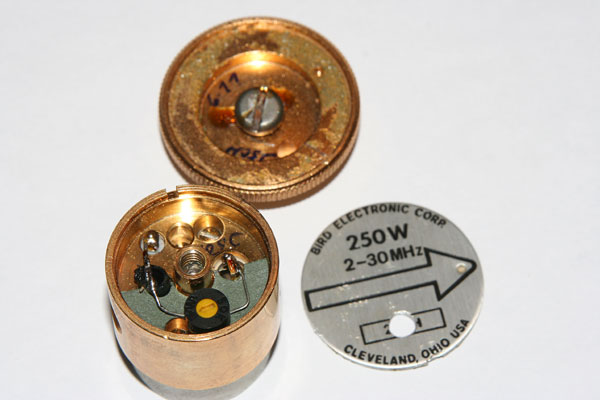
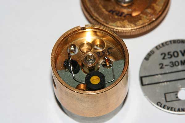
I needed a Bird slug for 500w.I have one for 250w (250H) reading on scale 0-250,first scale on meter.After have study this I try to adjust it for reading the middle of scale,0 to 500. I have a 100w transmitter I know giving out 100w on 52 ohm. I adjustet the probe with the pot down to read on middle scale 100w.Now.it seems to read correct as 500w probe.I will test out later if it is correct reading up to 500w.(Upper part of the meter).It is done. Result now,the 250H (250w) work fine with new adjustment. 1: 250H adjustet to 500H 5% on top of scale,just like 250H. 2: 250H adjustet to 1000H and top of scale 8% and 15% from 30w to 90w.Bird is connected to 52 resistive load in oil,1500w.To readjust the 250H to 500H work very fine.To adjust it as 1000H giving top bad tolerance.I get a new 1000H (1000w) probe from bird,testing the "new" 500H.Very close to the orginal spec.This probe 250H (250w),I work with a switch on front of the slug,to change between 250w/500w.
Now the project will go on to make a switch in front of the slug,then I have 1 probe as, 250w / 500w and 1000w 2-30Mhz,nice for amateur working.
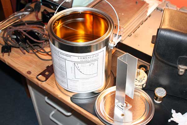
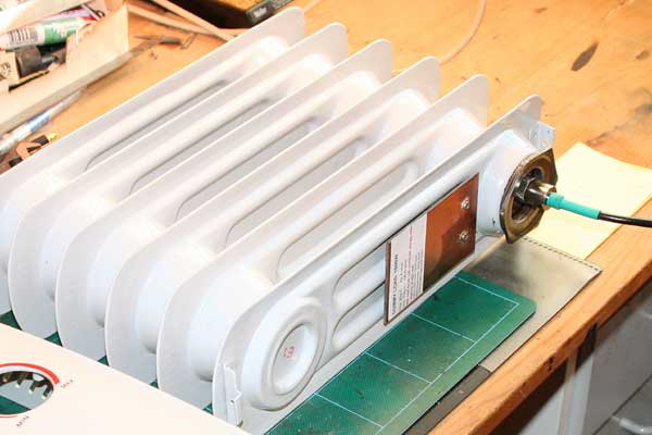
Dummy Load 50 ohm Project. The can, or closed oil system.

![]()
It is air between the oil and top and therefore no oil-cooling around this place. The heath from the resistive element going through the alluminium clamps and warm the top of the CAN. So after testing with 500w ca 8 minutes, it is going very warm from top and down to the half of the CAN. From here it is cold. The resistive element stay vertical into the CAN. This was a big problem,the oil around the resistor boiling very soon.
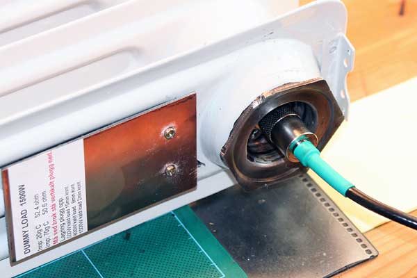
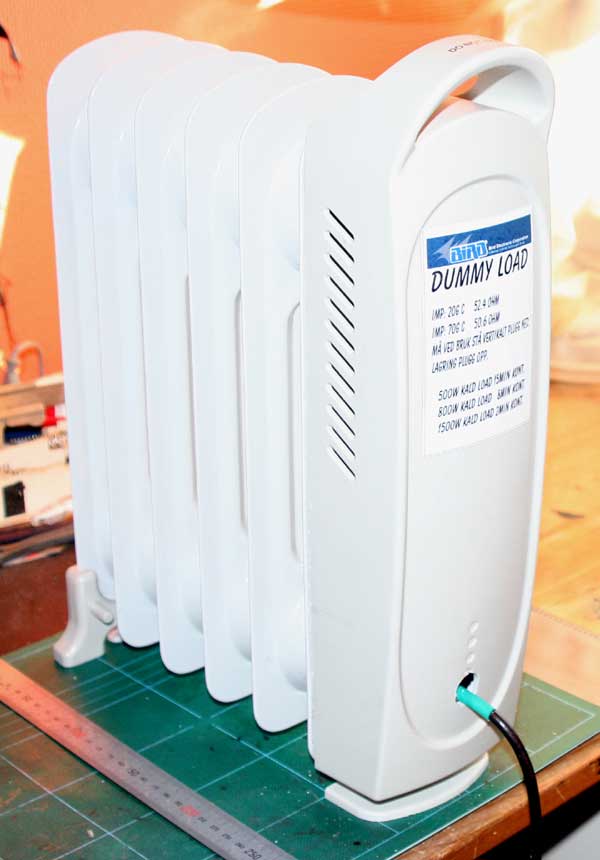
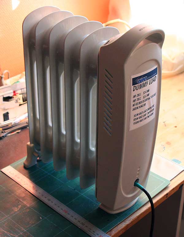
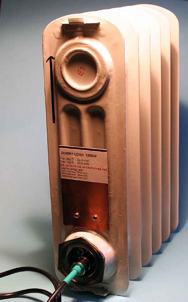
Now, I get a oil-owen from the store,for 800w 230v ac.I modefied the oil draining screw for PL-259. It was some tricky to get the PL-259 sealed.With some O-rubber rings this was no problem. Connections very like the orginal,but smaller tray. Now the resistive element was in horizontally possision when loaded.Inside it is now only 1.5l oil. Importent: After first test I warmed the oil very hot, then screw out the oil drain screw and then tighten it again. Now,the temperature is average all over the owen when keying the transmitter with 800w.
From cold (ca 20g C) it was possible to key the transmitter with 500w for 15-20 minutes.800w 8 minutter and 1500w possible 1-2 minutes,not testet. This test giving a regular temperature all over the surface, and you could easy hold the owen without no problem.I am now making a "Add On" fan for handling power around 3000w from the same unit. Result the closed oil system prefered.It is many times better than the "can" filled with oil.
According to the radio regulations in most countries, any licenced radio amateur must have a non-radiating load to connect to his transmitter's RF output. The use of such a load is mandatory for off-air adjustment of the transmitter
The load described here is capable of handling up to 10 watts of RF power for a couple of minutes, and is designed for the widely used 50 ohms impedance. It consists of ten parallel connected 560 ohms 1 watt resistors, R1 through R10, a voltage divider, R11-R12, and a rectifier D1-C1. Apart from loading the transmitter output with a minimum of reflected power, the dummy load also provides a direct voltage output to which a voltmeter may be connected to measure the RF power. If the dummy load is used for power levels higher than 10 watts simply use more, or higher wattage resistors to give a total of about 50 ohms. For instance, by using twenty 2 watt 1,200 ohms resistors instead of R1-R10 and 150 ohms resistors for R11 and R12, the dummy load is turned into a 40 watt version. The diode may be almost any Schottky type. Types like BAT85 and HSCH1001, for instance, are also suitable. Even a germanium type like the AA119 will work, but then for low powers only.
The dummy load is housed in a tin can of which the cover is used to mount the components. As illustrated, the ten 560 ohms resistors are soldered in a circlearound the center pin of the BNC socket. Their ground terminals are soldered flush to the inside of the cover. Capacitor C1 is a feed through type for which a small hole must be drilled in the cover. All resistors should be mounted with the shortest possible lead lengths to keep the reactive component of the dummy load as small as possible. After mounting the parts, the cover is fitted on to the tin can again, and soldered all around to seal the dummy load completely. Do not drill ventilation holes in the tin can because that will defeat the purpose of making a non-radiating load. The can may get quite hot when transmitter power is applied for a while, but that is no cause for concern.
The voltmeter read-out produced by the dummy load may be calibrated against a professional RF voltmeter (for instance a 'real' Bird Thruline). The voltages obtained at differebt RF power levels are noted so that a graph can be made. Depending on the reactive characteristics of the resistors used, the dummy load should exhibit a VSWR of less than 1.5 for frequencies up to 450 MHz. Resistors R13 may be omitted if the dummy load is always used with same voltmeter.
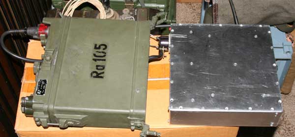
Project RA-105 (PRC-10) Power 12v unit. LA4JH
Moved project to the Web page "RA-105 Swedish Radio."
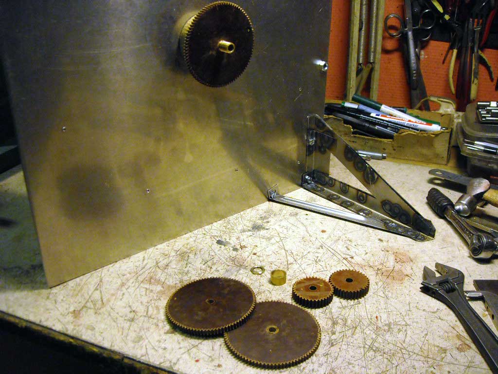
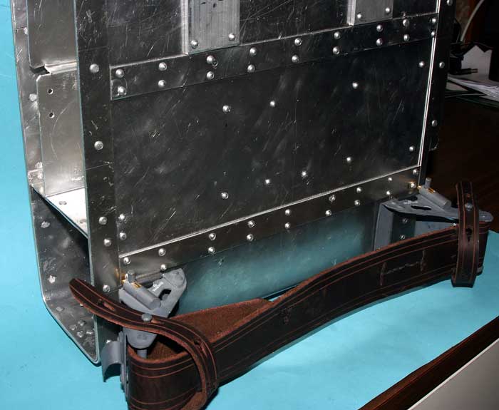
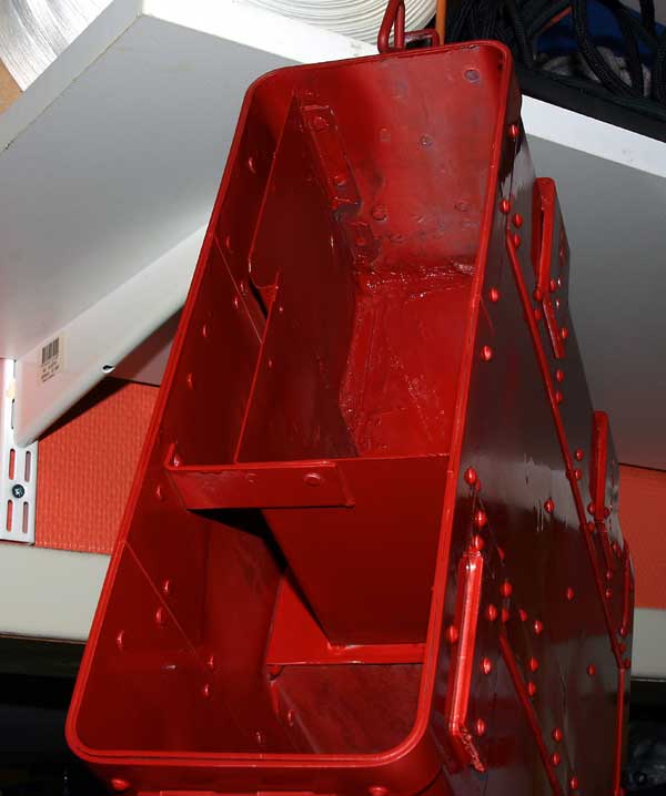
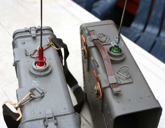
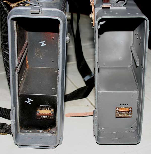
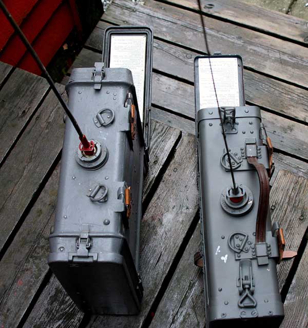
Project: Feld Fu.b box - repl alluminium.
As I understand,it is many Feld Fu units without the bakelite box around the world. After testing metodes of producing the Feldfu box,I concluded it was the best way using 2mm alluminium,form pressed corners and profiles.Inside as the orginal box.
What is worser than a old German radio, standing without a box?? Replica parts is better then nothing.Specially if you take the equipments out in the field some times.
Moulding the box was not a good ide.Result was making it from allu.First of all details was better connected together.It was stronger and giving mutch better distance from the transmitter.The groundplane was better than the orginal plastic case.A prototype is making.Special tools to bend the upper/under part of the case, was made.
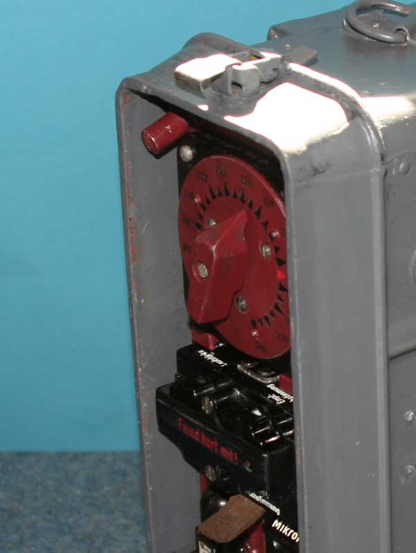
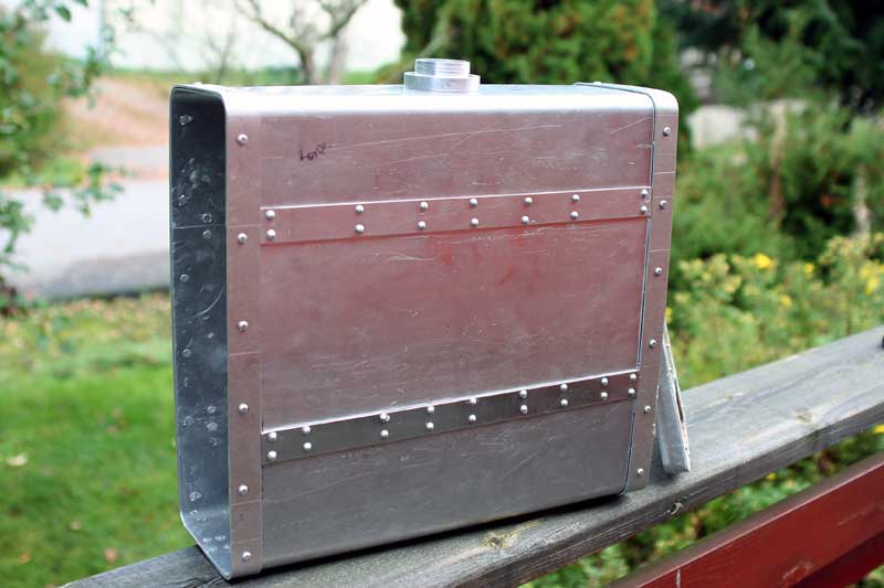

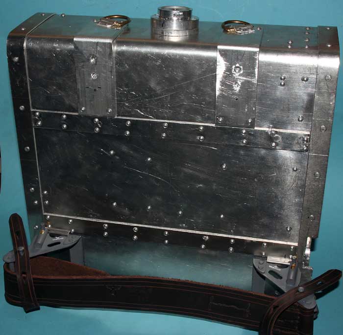

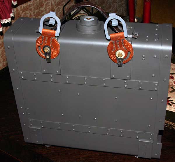


The Feldfu box have two productions types.It could been seen on the corners of the boxes.Type 2 have more strength around the corners. Type 2, i have only seen 2 radiounits with this boxes,so it is possible Horny A.G, make this on the factory.Type 2 is also on all frequency meter unit and charging units.
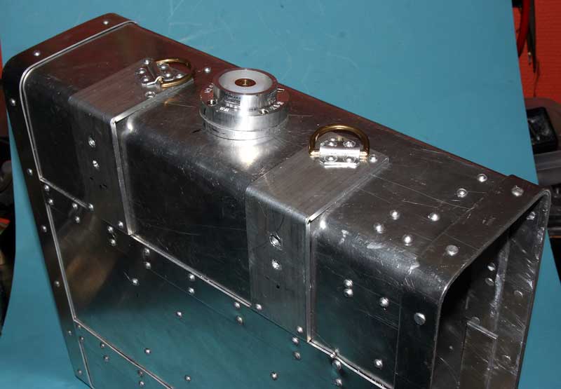
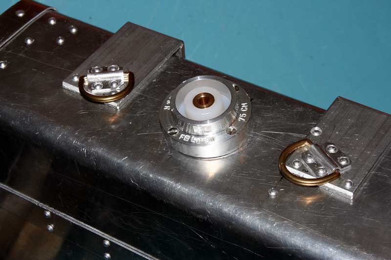
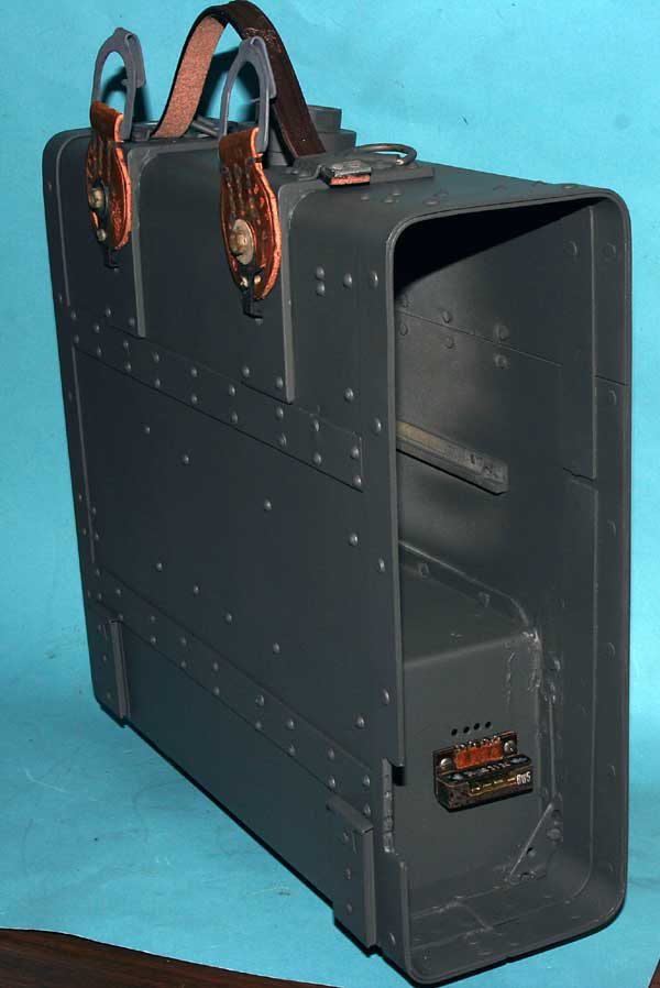
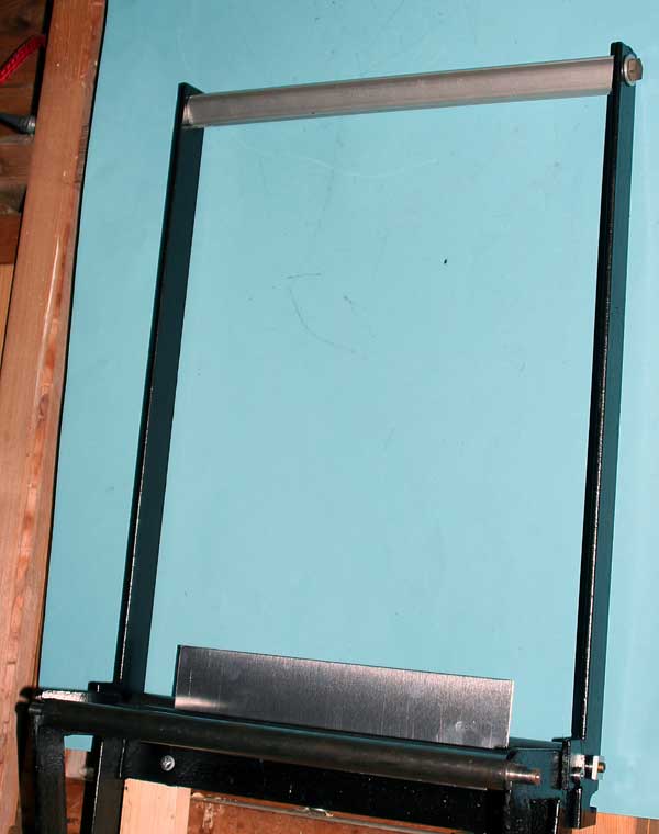
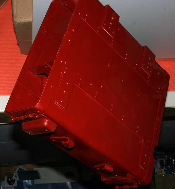
Proto type of the Feldfu box,as seen,in alluminium,was the best way to make a near possible box to this feldfu.Allu giving the streights,better than bakelite,and better groundplane radiations for the transmitter (150mw).It was nessesary to construct to special tools,one for the top and botten parts,bending the corners,and second, a smaller tools for bending the end, outer cover ,of the box.The box is finished and painted.Now,the end covers are constructed.
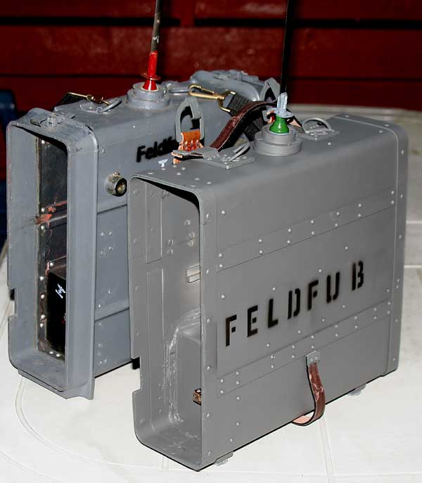
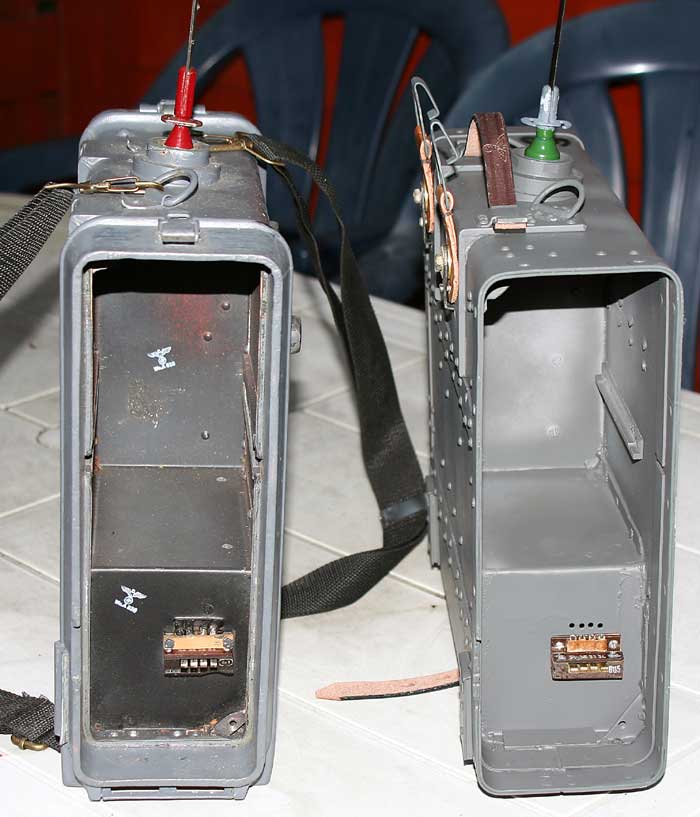
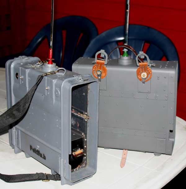

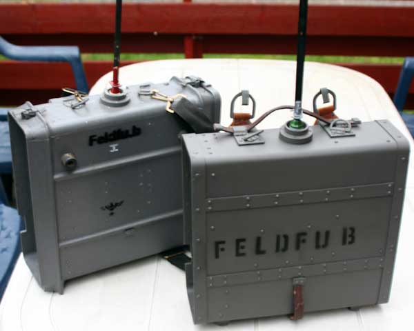
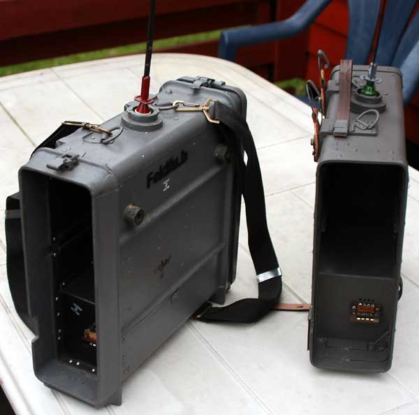
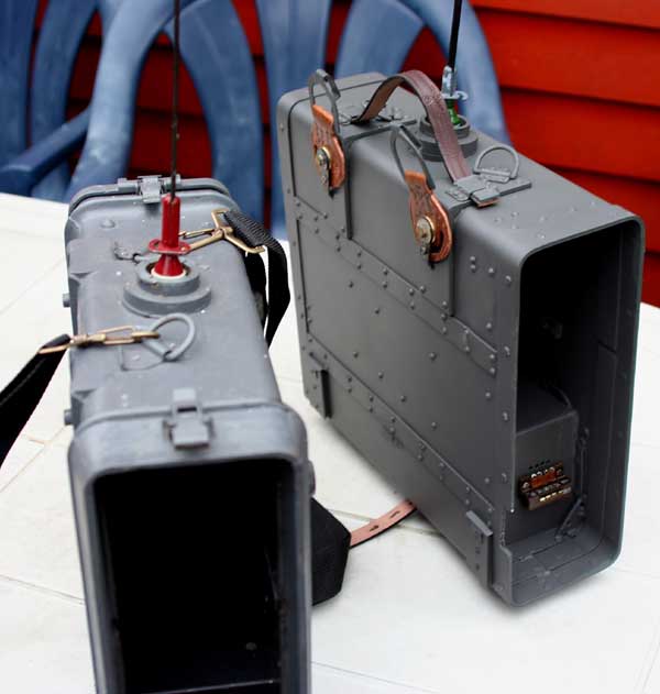

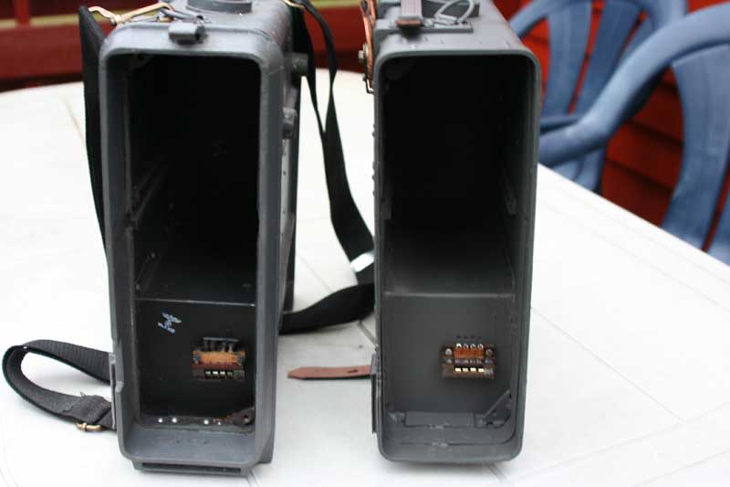
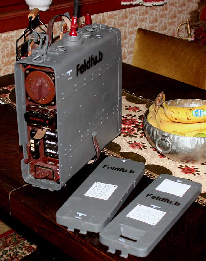


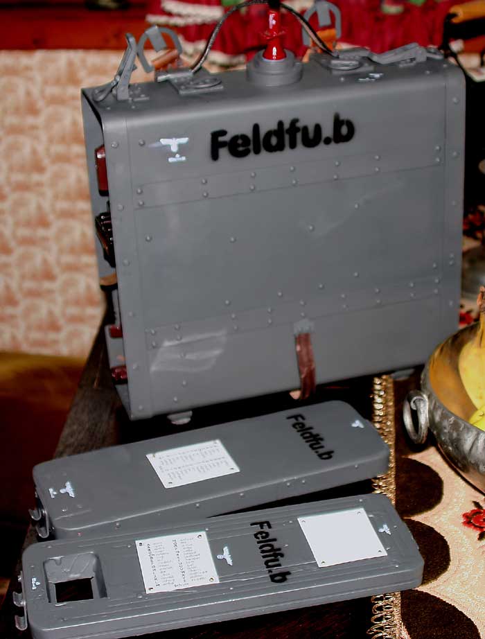
The orginal and the new together.

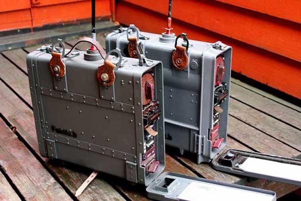
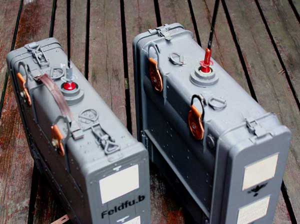
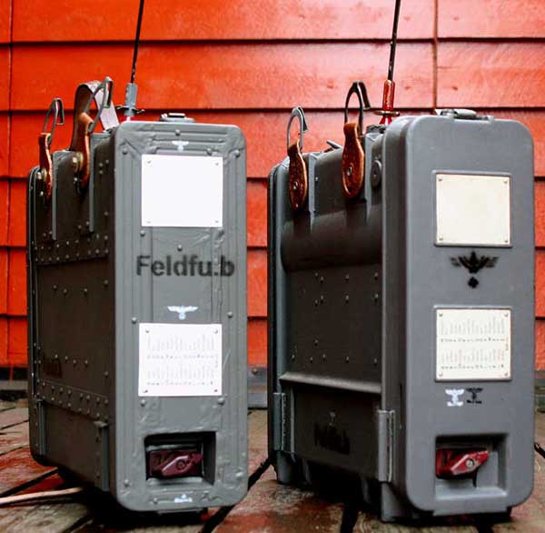
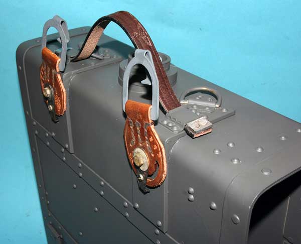
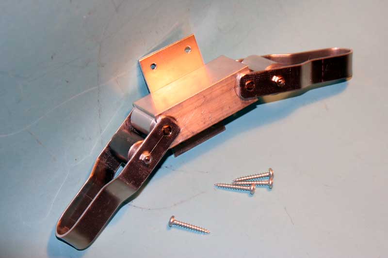
The locker on the top of the box will be mounted later as the end covers is finished.I will look at the box, to construct a "alloy rim",the rim strength for the bakelite alloy.It will be only for the cosmetics.The replica box is many times more secure for destroying in the field.
Project: Mechanical Vibrator WGl.2,4a changed with electronic "vibrator" LA4JH
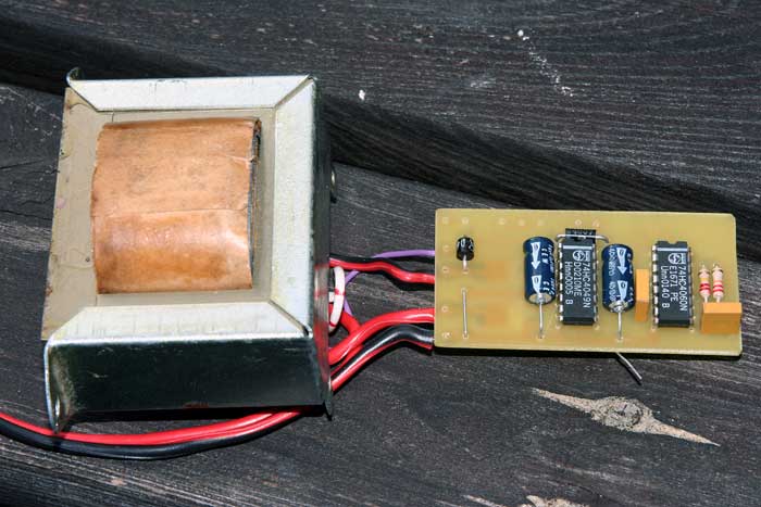
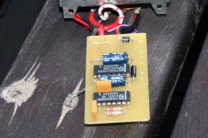 This project going on page "Tornfu.g".testet and
working well.
This project going on page "Tornfu.g".testet and
working well.
This site was last updated 09/09/16 Home

.jpg)